Having filled about every bit of space with metal working machines, there was nothing left over for woodworking. Eventually however, moving the laundry to the second floor freed up a basement room (With kids gone, there were too many empty bedrooms upstairs!)
The old laundry room isn’t large but if I was going to do working, it had to be working from rough; i.e. table saw, jointer, planer and bandsaw were required as well as a bench.
I pine for a Felder machine but space doesn’t allow it. The Inca line of tools seemed the right choice. Inca is some acronym for aluminum die casting so they are light machines. They are also small which is good and being Swiss are of reasonable quality (although still consumer not, not like a Swiss machine tool). Like so many things quality they are no longer made, however can found second hand.
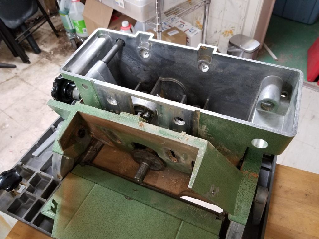
To disassemble the saw, the shaft has to come out which seems to present some minor challenges.
Its always a concern taking something apart when its secrets are unknown…. does it just need a bit more force, or have I mistaken what is going on and what is holding what?
Don’t rush in, think it through and most of time you can rationalize backward as to how the designer went about things.
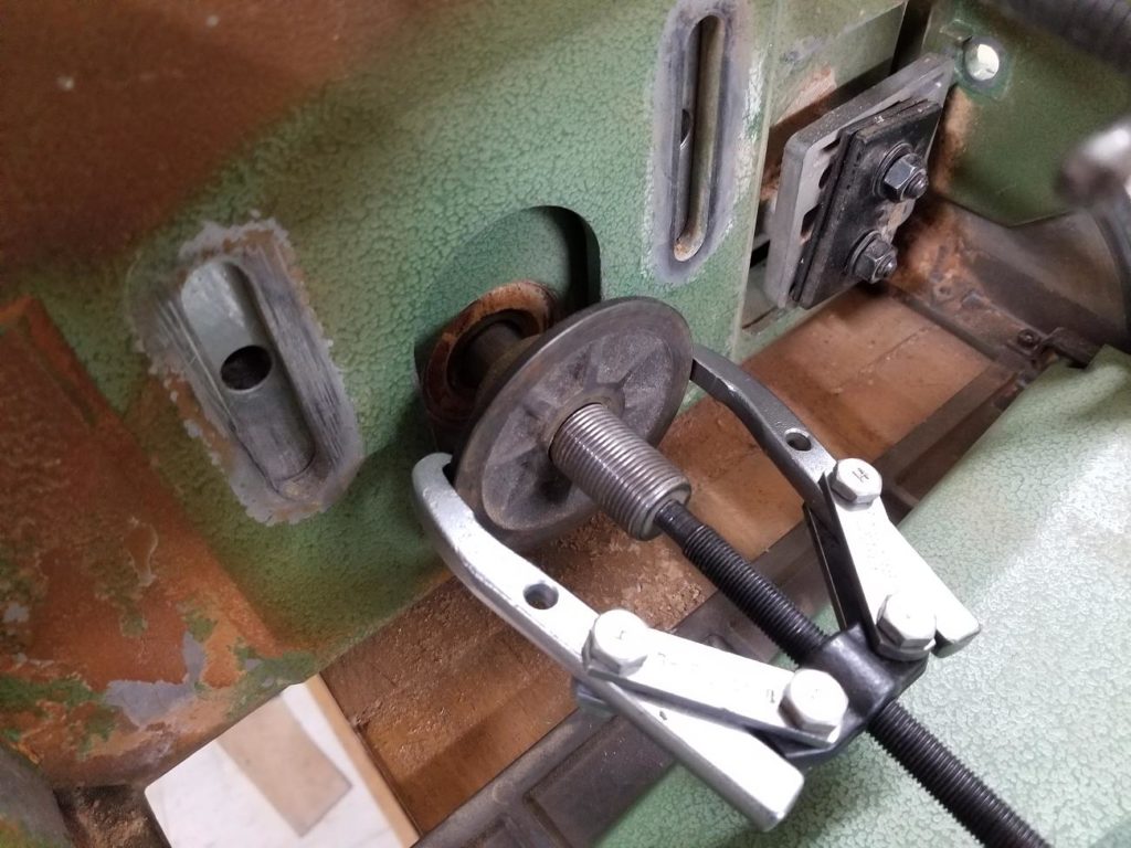
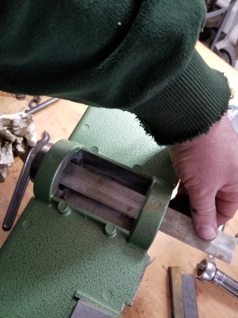
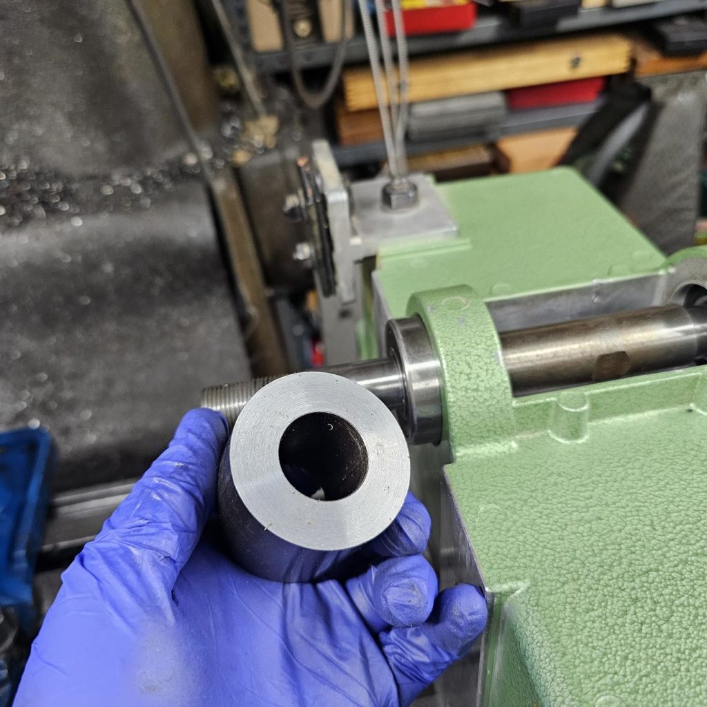
The flange for the saw wouldn’t budge by hand, but it easily came off with a puller. Its a very light interference fit, indicative of quality in that fine fits are harder to achieve and you sure don’t want this part wobbling on the shaft.
Lo
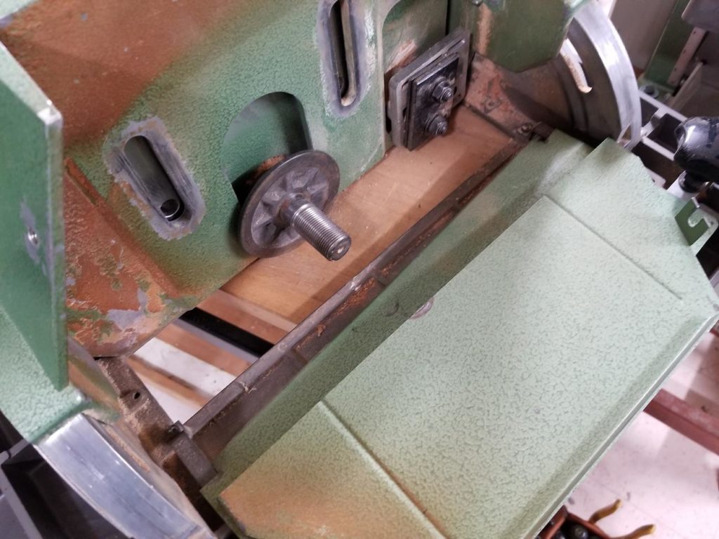
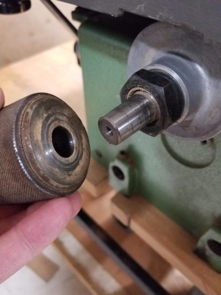
On the other side, the drill chuck has to come off first. Its a typical taper mount. The nut which retains the pulley is used to press off the chuck
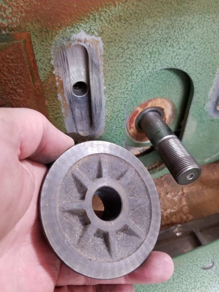
The pulley then slides off – don’t lose the Woodruff key!
Now what to do?
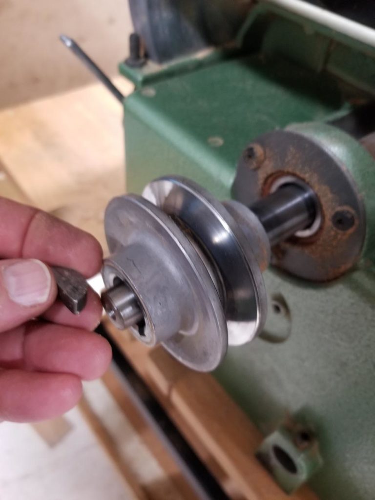
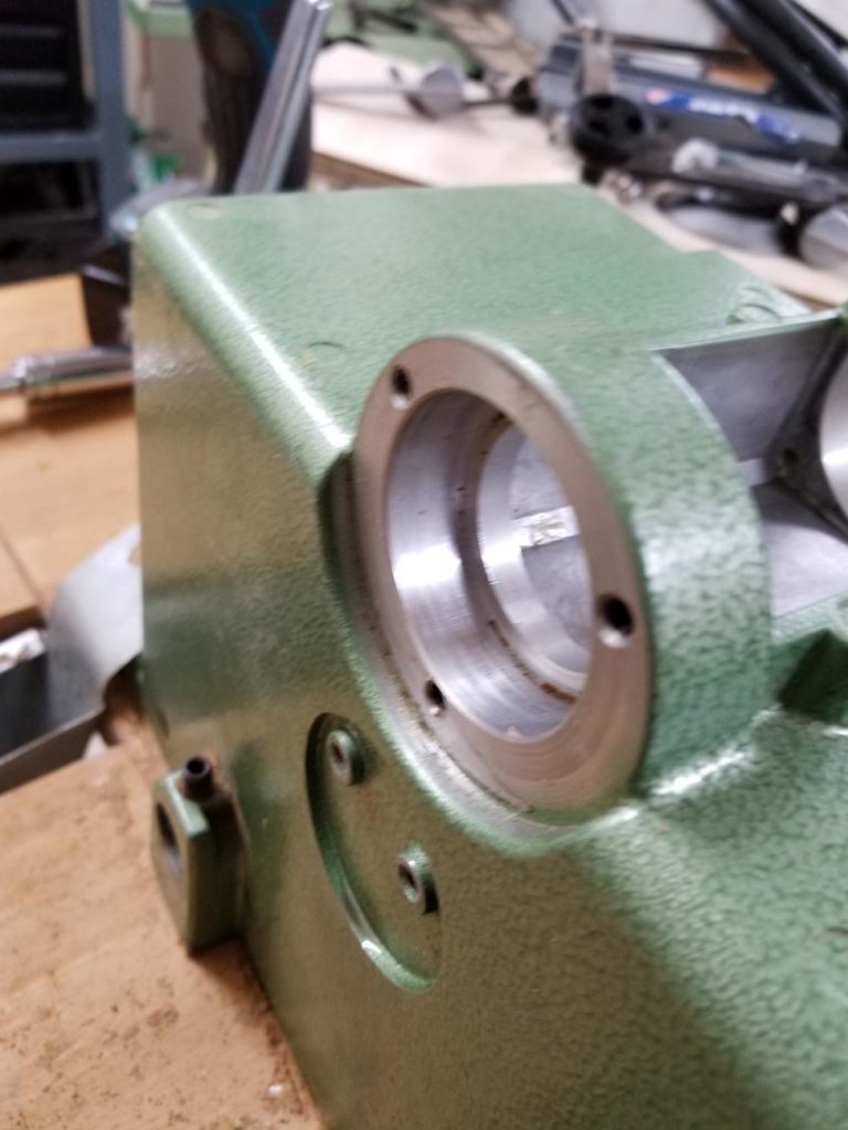
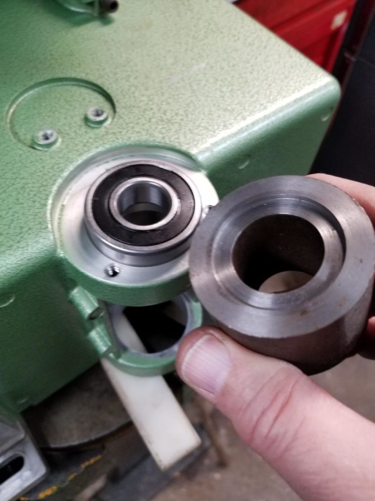
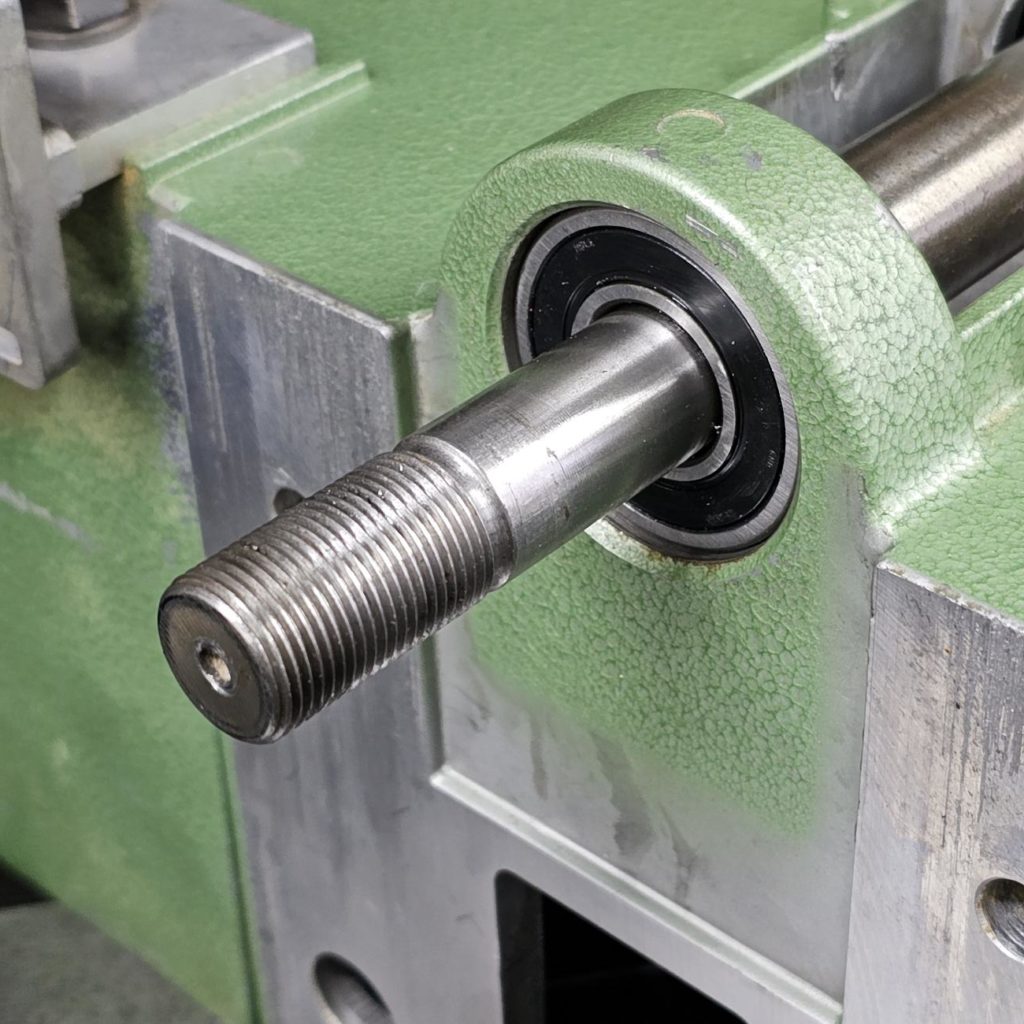
Typical bearing arrangements on a spindle would have one bearing fixed and one floating. This machine is no exception. The pulley side bearing rests against a shoulder in the casting and is held in place with a plate and three screws (see photo below)
There is no shoulder holding the other bearing in position, it can float within the housing. The reason for this is that as the shaft warms and expands, this allows the bearing to move slightly so things don’t bind.
The other thing that typifies bearing arrangements is that the bearing is usually an interference fit (press fit) in the rotating race (in this case, and most of the time, the inner race), and a close sliding fit on the other race.
The challenge here, is where is the interference fit and how to do we get things apart?
First off, removal means new bearings. You should never apply force through the rolling elements (the balls) which is about impossible to achieve when disassembling.
Because there is the shoulder on the pulley side, the shaft can’t come out that way. If you tried, the saw side bearing would stay on the shaft but wouldn’t get past shoulder. That would leave one stuck as you couldn’t get a puller in the remove the bearing.
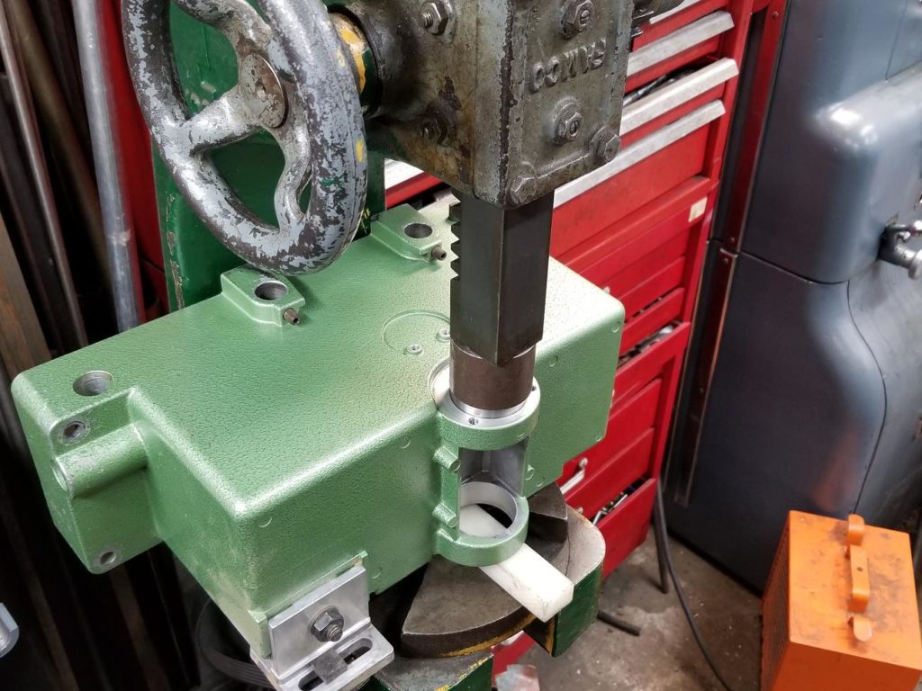
The shaft must be removed by applying force on the pulley side so it comes out the saw blade side.
Use lots of little hits rather than gigantic wallops (that’s how to minimize the chance of breaking anything) and protect the end with a piece of wood
A squirt of penetrating oil is a good idea as well, it aides the sliding of the tightly fitted parts
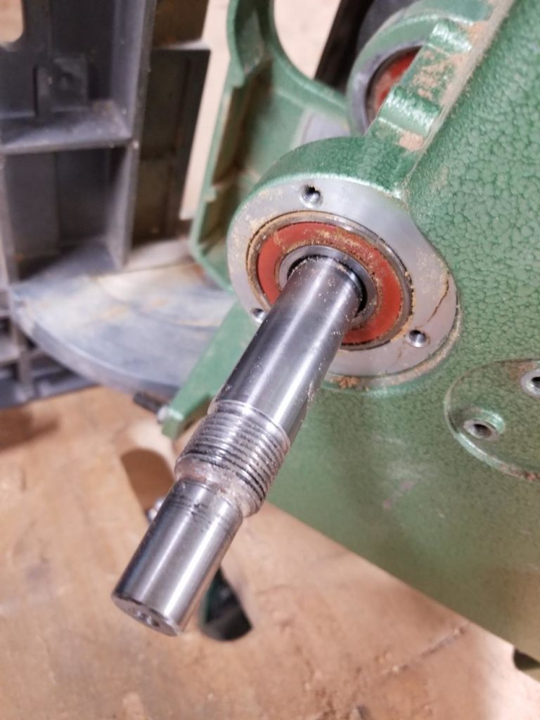
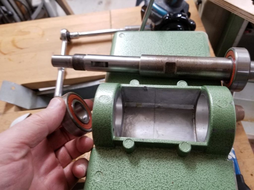
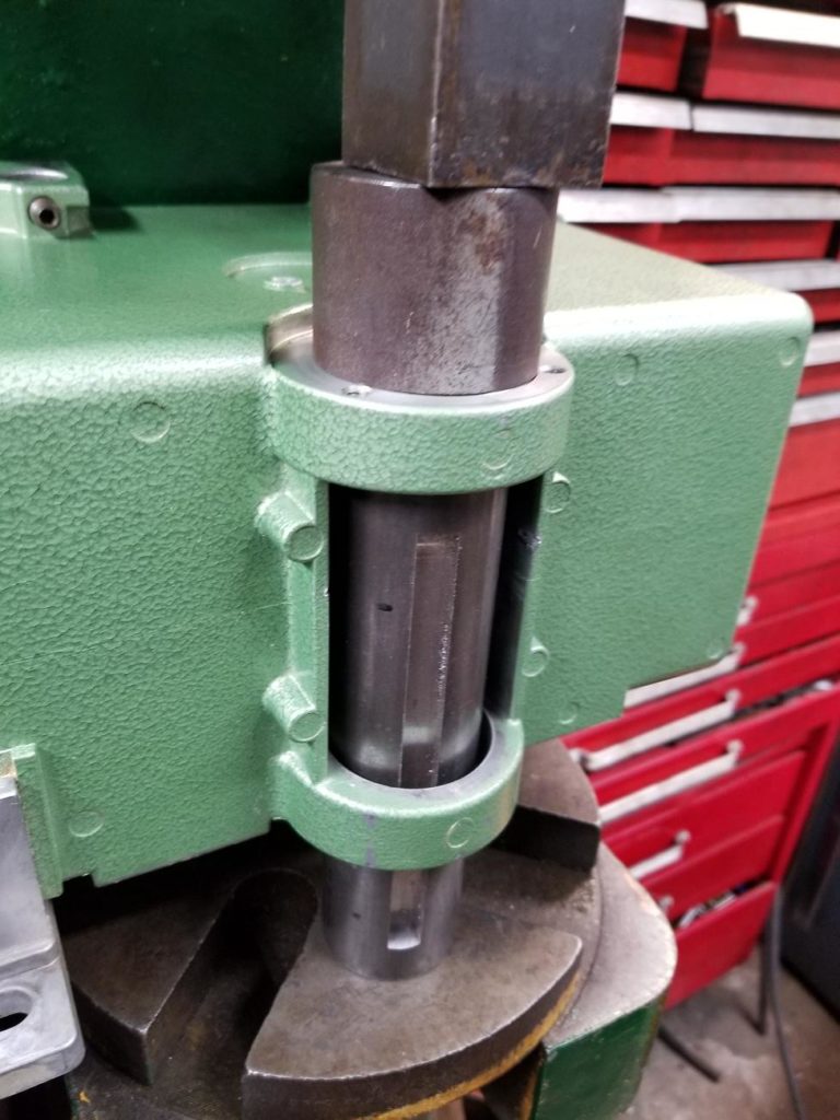
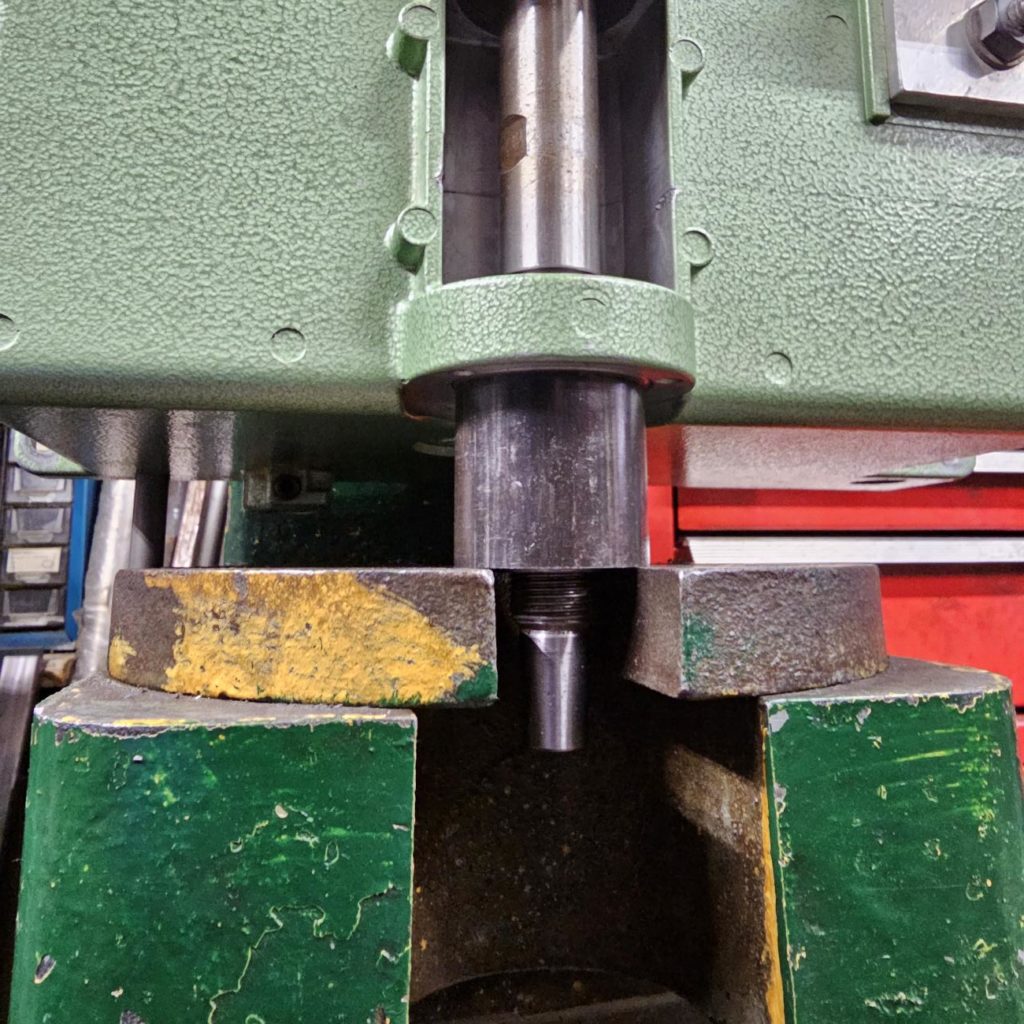
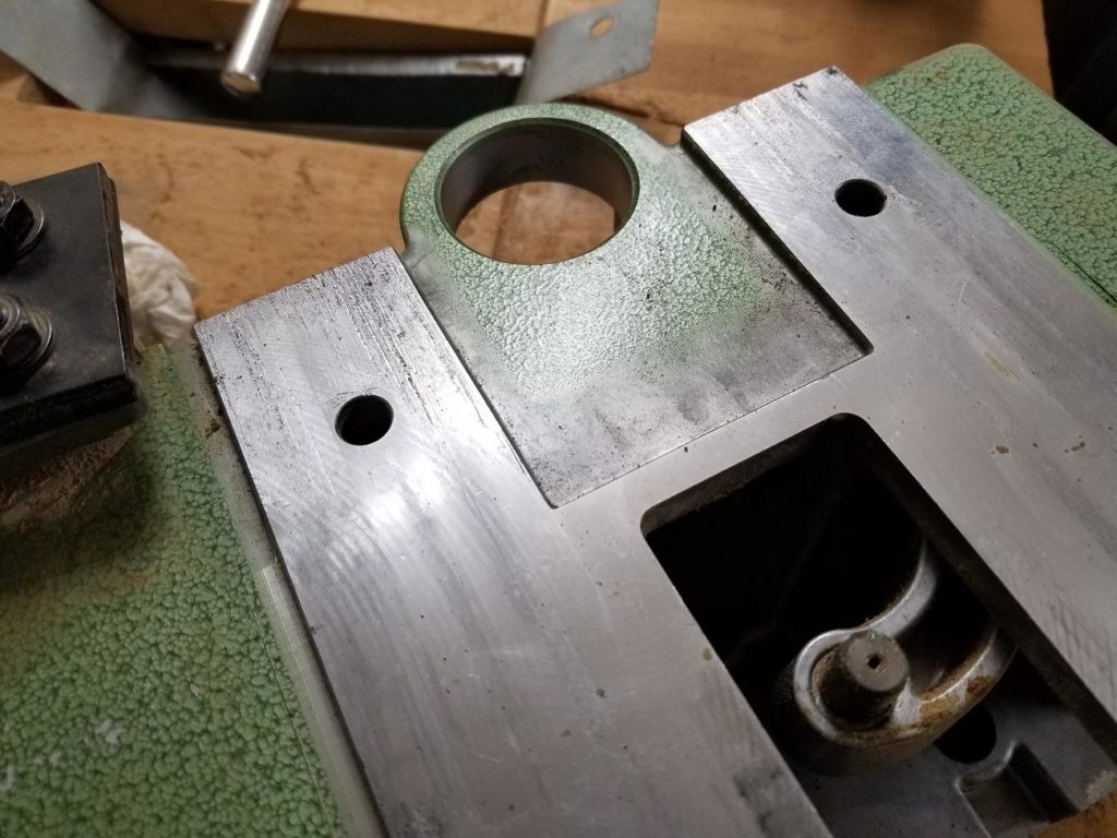
This photo is to show the shoulder on the pulley side.
After you get the shaft out, tap out the bearing left in pulley side bore
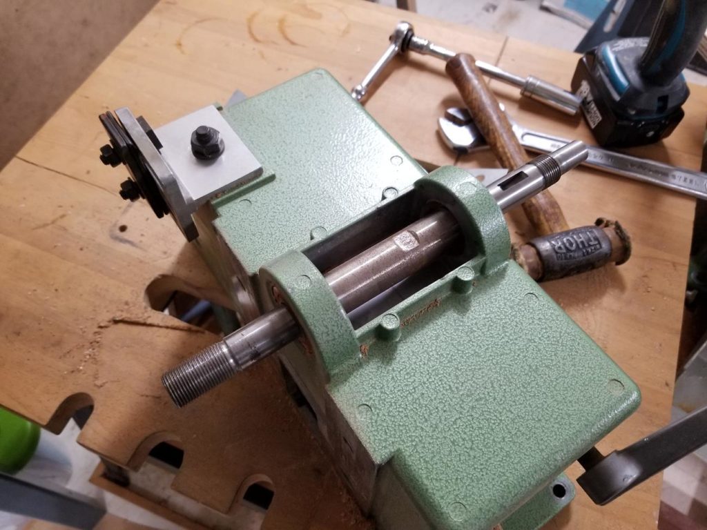
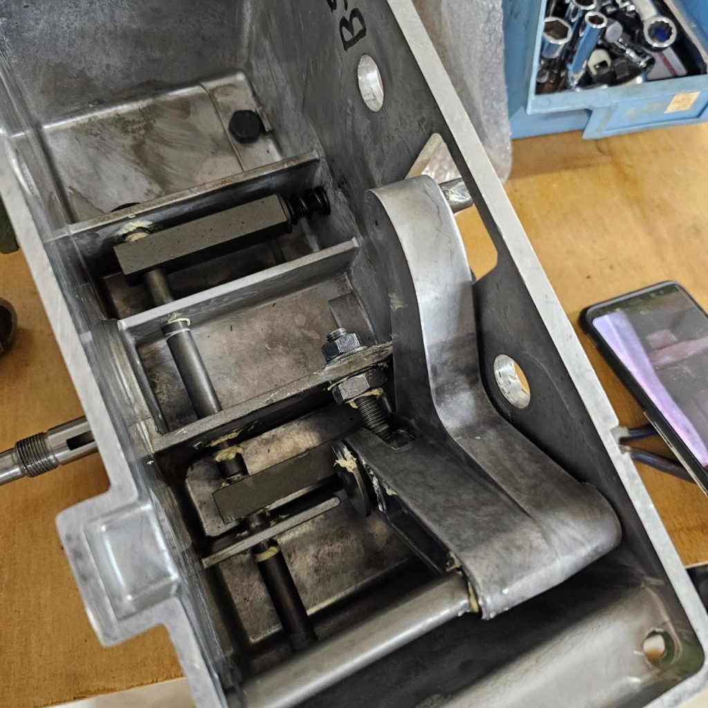
Progress so far.
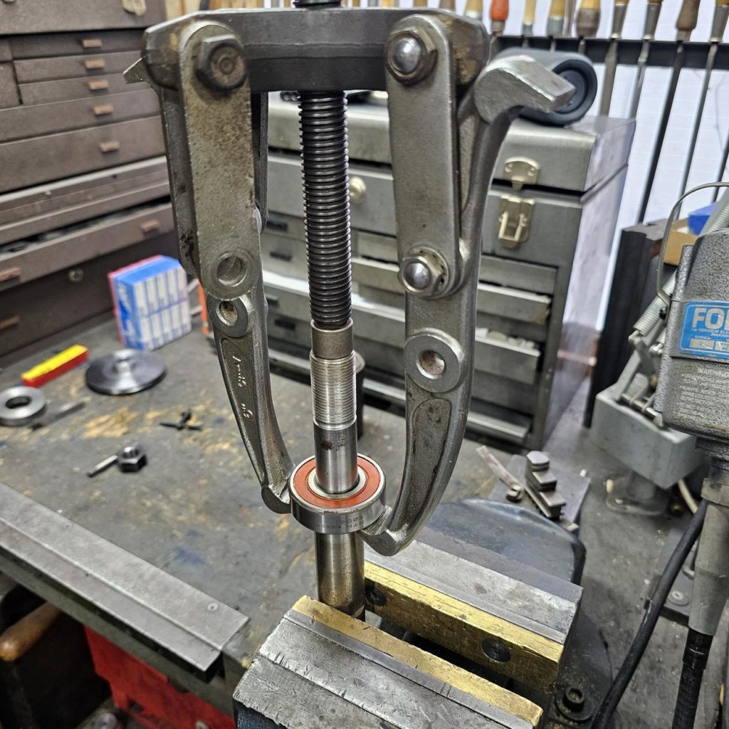
Its an easy job to pull the remaining bearing from the shaft.
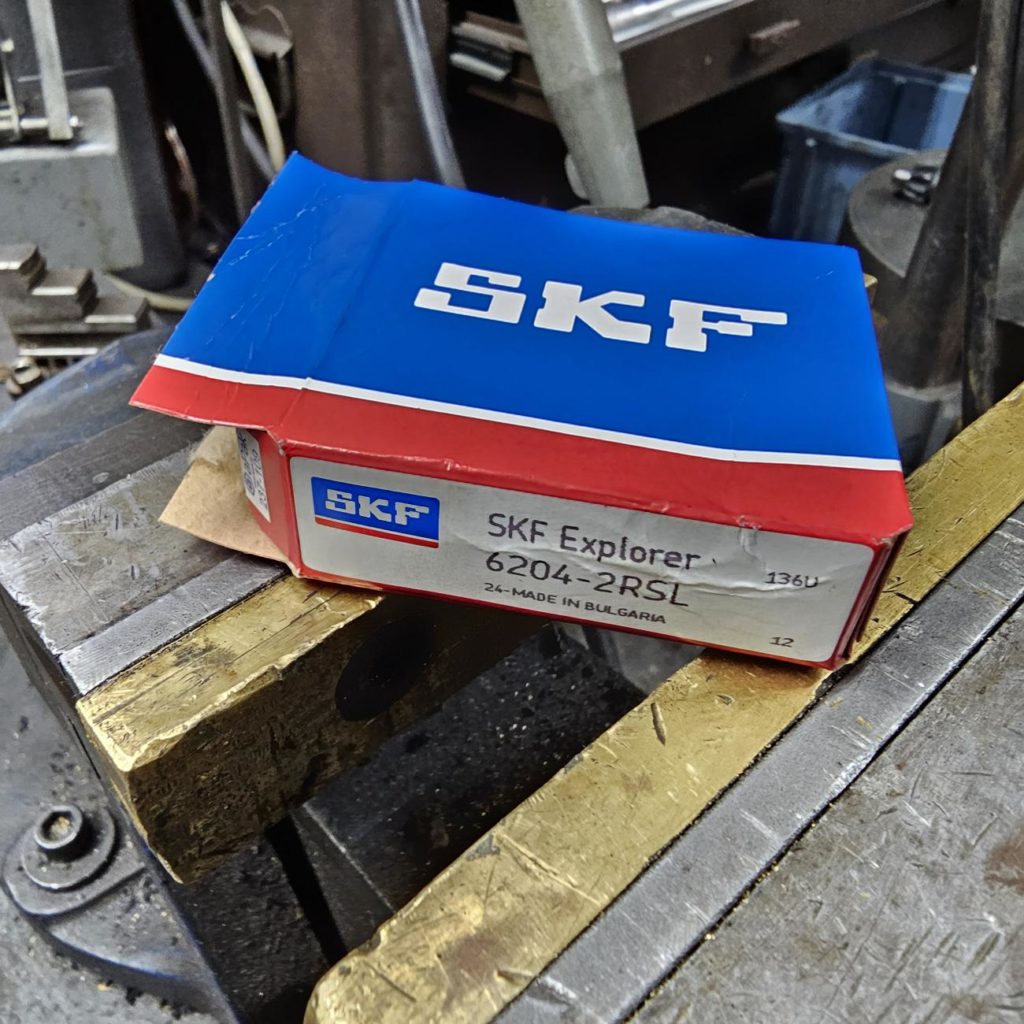
You need two 6204 bearings to complete the job. They are about the most common bearings on planet and will be available until the end of time so are easy to procure.
Don’t use cheap, crappy bearings. These are made in such high volumes the prices for the good ones are very reasonable.
Also, use 2RSL bearings. These are the newer technology low friction seals. Its gives the best of both worlds; low friction like shields, but with seal like protection.
Assembly is essentially the reverse of disassembly, however great care has to be taken to NEVER apply force through the rolling elements, in this case the balls. That will brinel the bearings and cause them to fail rather quickly.
If that’s not clear, look at this way: you have an interference fit of a bearing you want to install on a shaft. If you press it on by contact with the inner race, everything is fine. However if you press it on through the outer race, the force is applied through balls which will cause damage. If the interference fit were on the outer race, that you would have to press on the outer race to avoid damaging the bearing.
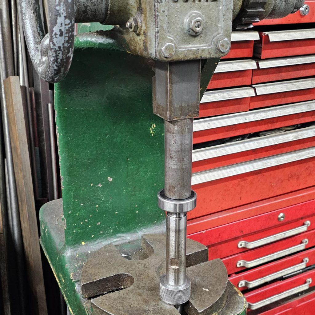
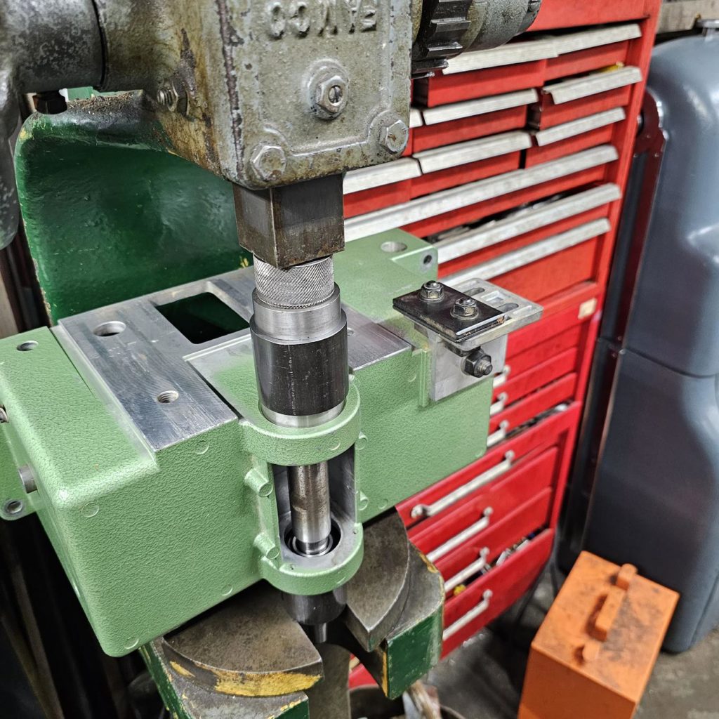
You can see in the photo I’ve a length of tubing used to press the bearing on that is only contacting the inner race.
Notice the end of the tube is machined; it has had facing cut done so it makes even contact with the race
Next, a new bearing is pressed into the pulley side of the housing (the one with the shoulder).
Be careful, this should be a light press however the aluminum looks like it could easily be snapped.
Do use some lubricant, a bit of oil, when pressing parts together.
Note the turned piece made so it only presses on the outer race.
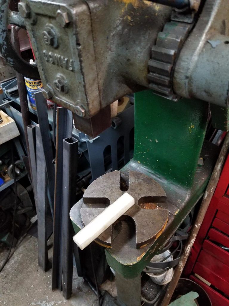
I started like this, but chickened out.
Ahh, much better. The underside of the aluminum casting, where the should is, is supported by a steel bar in the press table.
This eliminates any chance of breaking the casting
This work requires a lathe to make sure you can all the right blocking you need to press things properly, but as I say to wife, I’m not sure how people make it through their days without a lathe, so hopefully you have one.
If you don’t have a lathe, get someone to turn such blocking. Its not really possible to do a risk free installation that doesn’t damage the bearings without this sort of care in how and where force is applied to press the bearings in.
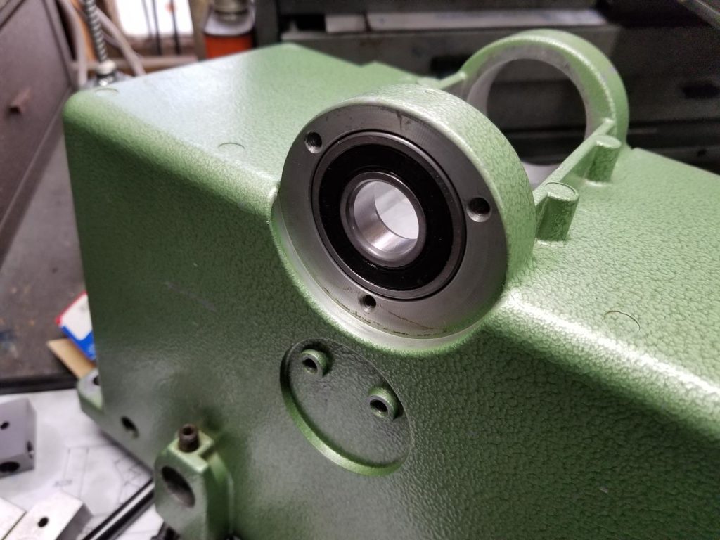
Bearing installed.
Things get slightly more complicated now.
We have a bearing in the housing, and a bearing on the shaft. I’ll call the pulley side bearing the bottom bearing because of how things will be oriented in the press.
Both bearings need their inner and outer races supported. The top bearing is bearing pressed into the housing, but the inner races also needs to be supported as the shaft will be pressing into the bottom bearing’s inner race.
The solution again is to turn blocks that fit the bearings
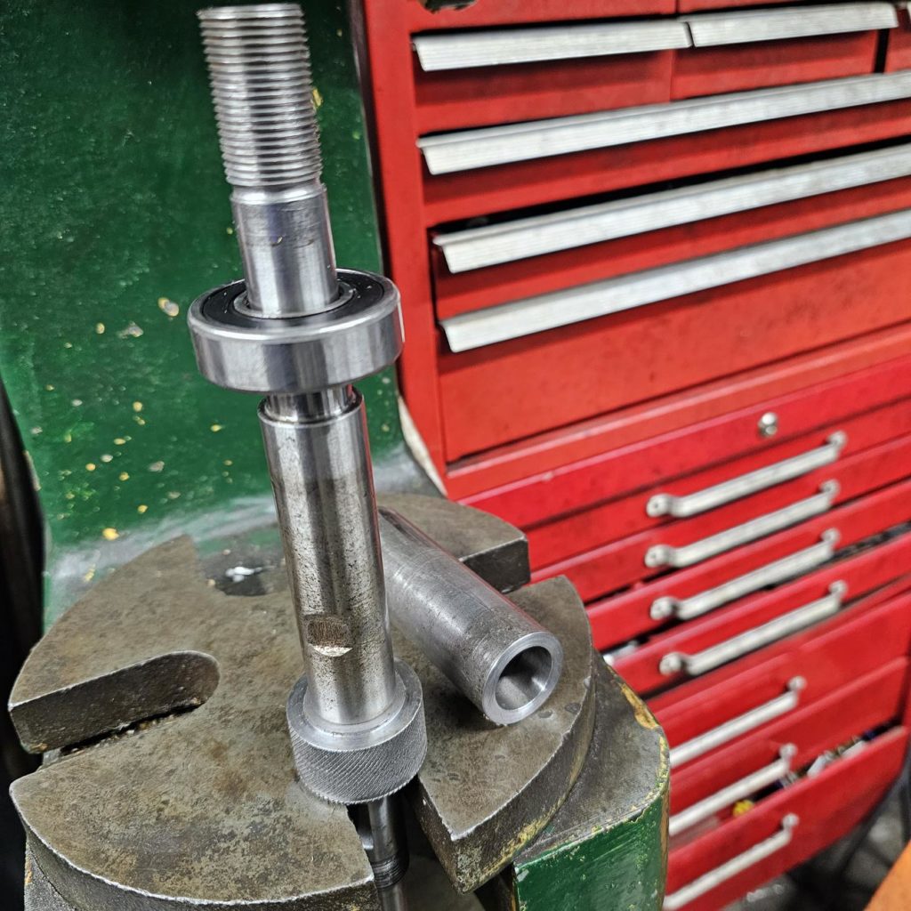
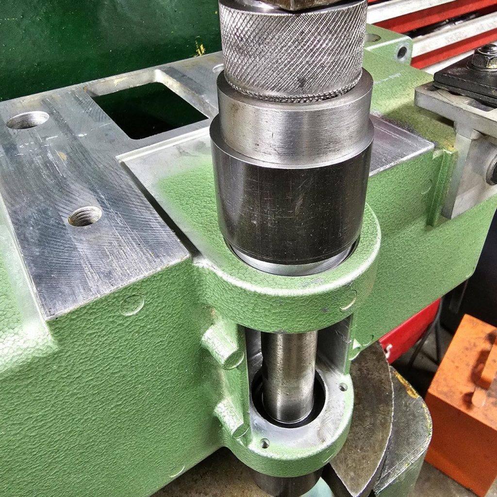
Here is the overall setup.
Details of the bottom bearing support, contacting the inner and outer race
Everything is working well.
And the shaft and bearing assembly is complete!
Clean and lube everything. Replace or rebush if there is excessive wear
I had some galling on the table height adjustment surface. I removed any protrusions with a burr file , concluded it was more that serviceable and reassembled with lots of lithium grease