Ideas

Techniques, processes, beliefs and mysteries

Cutting Speeds for beginners B

You’re surfin’the web for kicks and giggles, who wants a dose of dry  old theory?

Please Dear Reader, Dear aspiring Metal Craftsman, suffer through this no matter what.  Why?  Its the basis of machining, not that hard and applicable to every machining operation.  Read it again if the penny doesn’t drop the first time. 

Things to believe in: 
 

  1. the speed is how fast the tool is traveling relative to the work.
  2. Speed could be stated lots of ways, MPH, KPH and so on but for us FPM feet per minute is the usually unit
  3. If work is spinning the lathe, the surface of the work is traveling past the tool tip at so many feet per minute.
  4. If milling, the tip of cutting is passing over the surface of the work at so many feet per minute
  5. If drilling….and so on
  6. For each type of tool material (e.g. HSS, Carbide) there is an optimal cutting speed (in FPM) for each type of work (e.g. steel, brass, aluminum)
  7. Optimal means its as fast as the tool can go before you get excessive tool wear.
  8. One way of expressing this, is that tool wear is linear up to the cutting speed.
 
 
MaterialCutting Speed with HSSCutting Speed with Carbide
Steel100300
Aluminium3001000
Chrome Moly Steels60-80200
Tool Steel (annealed)80200
Cast Iron100250
Brass200500
Bronze60150
Stainlessslow, i.e. 30 Feed should be the the determinant; i.e. on each revolution it has to be enough to get under the work hardened zone100 + same.

Using a Wiggler

The wiggler is a super handy tool that seemingly a lot of people aren’t familiar with.

With the ball end its becomes and edge finder or the pointed end is useful for indicating work in the four jaw.  However one its most useful functions (and what the pointed end is intended for) is to pick the spindle axis. 

The point is centred as per the video.  This sharp point can then be lowered to the work in the drill press or mill as a way to locate the spindle over scribed lines or an edge.

For many jobs, its more than accurate enough to achieve the required tolerances making it the right tool for the job


Deep Hole Drilling

Here’s a very effective little trick to drill long deep straight holes – no small feat!

The popular refrain is “use a gun drill”.  I say if the person asking the question had a gun drill and pressuraized hydraulic system to use it with, they would querying how to drill deep holes

Fortunately there is an easy way.  I’ve drilled holes over 30 diameter deep and they comeout with a thou or two.  Here’s how.  The only special tooling required is to silver solder extensions on to the required reamers and drills

The Procedure for say 1/8″ (which i just did so remember the steps):

1) spot drill.
2) drill 3/8″ deep with a #37 twist drill, .104.
3) with a boring bar (or head) counter bore .117 /say 1/4 deep – this starts things straight
4) ream to end #31, .120
5) spot end of hole using #31 drill – go no distance, just spot the hole, This is crucial and will ensure the spot is concentric for the next step
6) switch back to #37 drill bit, drill 3/8
7) ream #31 to end
8) go to 5 until you break through
9) run a 1/8 reamer through and it’ll be darn near perfect

Reamers of course cut on the ends as do twist drills. this sort of leap frogging keeps whats been drilled/reamed well guided by hole so far.

In this case i ground the 31 and 37 drill bits in a T&CG so i could rely on their sizing….this is not critical or the source of the accuracy but without a t&cg or good drill grinder it probably wouldn’t hurt to start with a new drill bit


Silver Soldering

Silver solder (a brazing process) affords two advantages over solf solder:  It holds at higher temperatures such as on a boiler and it has about 10x the tensile strength of soft solder.  Silver solder by the way, is solder with greater than 50% silver.  The so called silver bearing solders (around 5%) are not silver solder.  There are lots more complexities (and differing nomenclature) you can study, however the this ought to give you a fighting chance at some basic shop successes with silver solder

We must use SS for example in model copper boilers where the joint needs the extra strength as well as being able to perform at elevated temperatures

Beyond the must use, I would suggest its use when the strength is of benefit and the extra heat its application requires won’t damage things. 

To silver solder, there are a couple of key points.  Have clean surfaces and use lots of flux are key. 

I also extensively use Kozo Hiraoka’s (a prolific author gracing the pages of Live Steam magazine) technique of cutting little bits of SS and setting them in the flux prior to heating.  You must be careful not to blow the SS away with the torch, however these lead to exceptionally neat joints with messy blobs of excess solder.  Using this approach, 1/16″ diameter SS is the size to buy.

Set up and Heat Sources:  Get some insulated firebricks and SS on top of them.  Note “insulated”, regular fire bricks won’t do.  The IFB reflect almost all of the heat back, whereas firebricks are heavy and absorb heat.

For a heat source, I mostly use propane and air.  It is more than hot enough however is less likely than oxy/acetylene to burn the flux (wrecking the chance of a good joint)

For large work pieces, I use O/A.  We don’t need temperatures any hotter than what propane/air is capable of, however the high temps of O/A means we can put a lot more heat into a work piece in a shorter period of time.  When using O/A , its especially important to concentrate the heat around the joint and don’t play the flame directly on the flux/solder

When to Soft Solder

The disadvantage of soft solder for certain applications is also its advantage in others – its low melting point.

This means you can make good joints without dangerously heating the parts.  The sheet metal gas tank in the photos for example.  This thin brass would become horribly warped if you tried to silver solder it.

Another important factor is the affect heat has on the metallurgy of the work.  Brass for example as bought for example is “half hard”.   If  you take it up to silver soldering temps, you’ve taken it well above its annealing temp so have altered the material substantially.

I was surprised to lean that many are surprised to learn that you can soft solder steel.  This most easily done by tinning both surfaces first – flux the surface, warm, then apply solder.  I use a paper towel to spread the solder around and wipe of any excess.

Soldering steel is a very handy work holding technique.  When you need work a thin piece or something where need access to the top and sides in the say the mill, just sold solder the work to a bit of scrap steel and have at it!


Disassembly - taking it apart

Here’s some pointers on taking things apart I’ve learned over the years.   The goal is  “Create no Damage”. 

Rule 1.  Risky prolixity, the first note is to stay calm; think it through.  When I’ve messed something up its often because I’m pursuing a way of taking it apart, it doesn’t work, so like a dog with a bone I intensify and more force is applied.  This doesn’t end well, better to walk away and rethink.

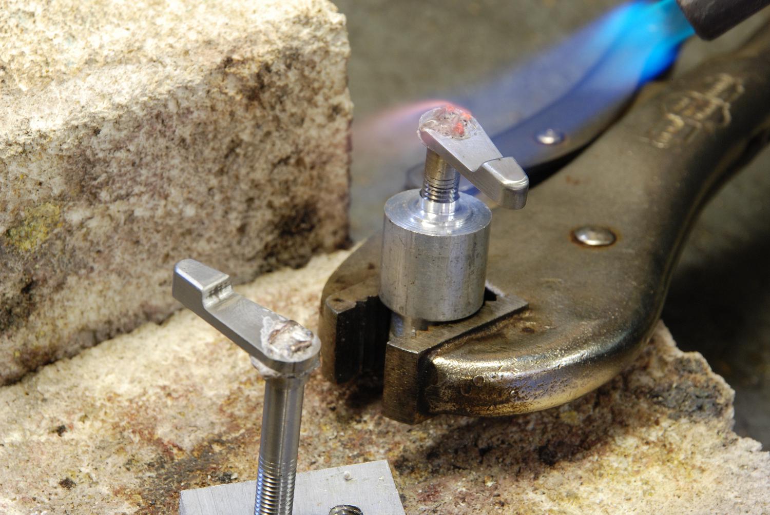
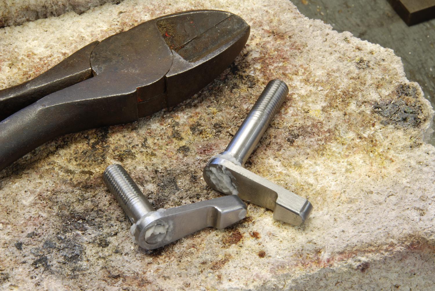
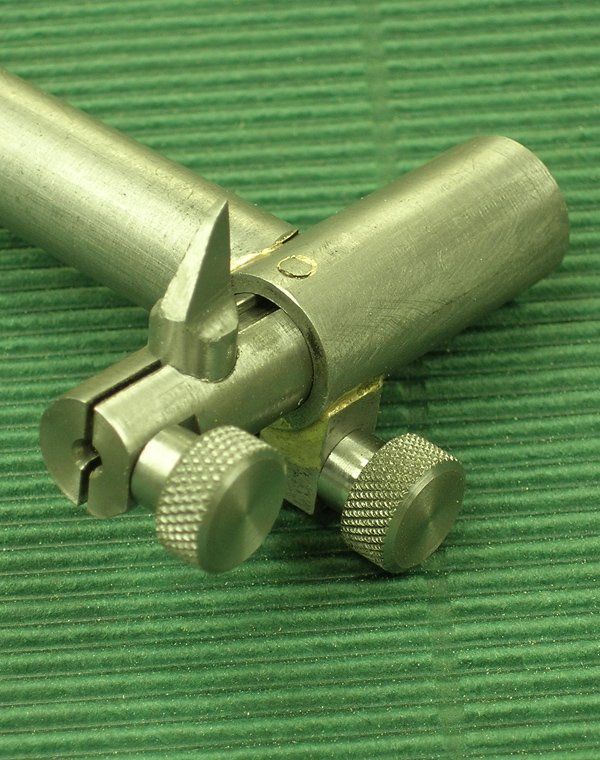
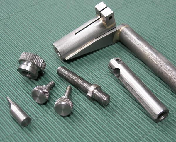
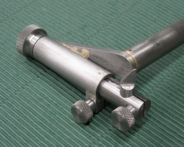
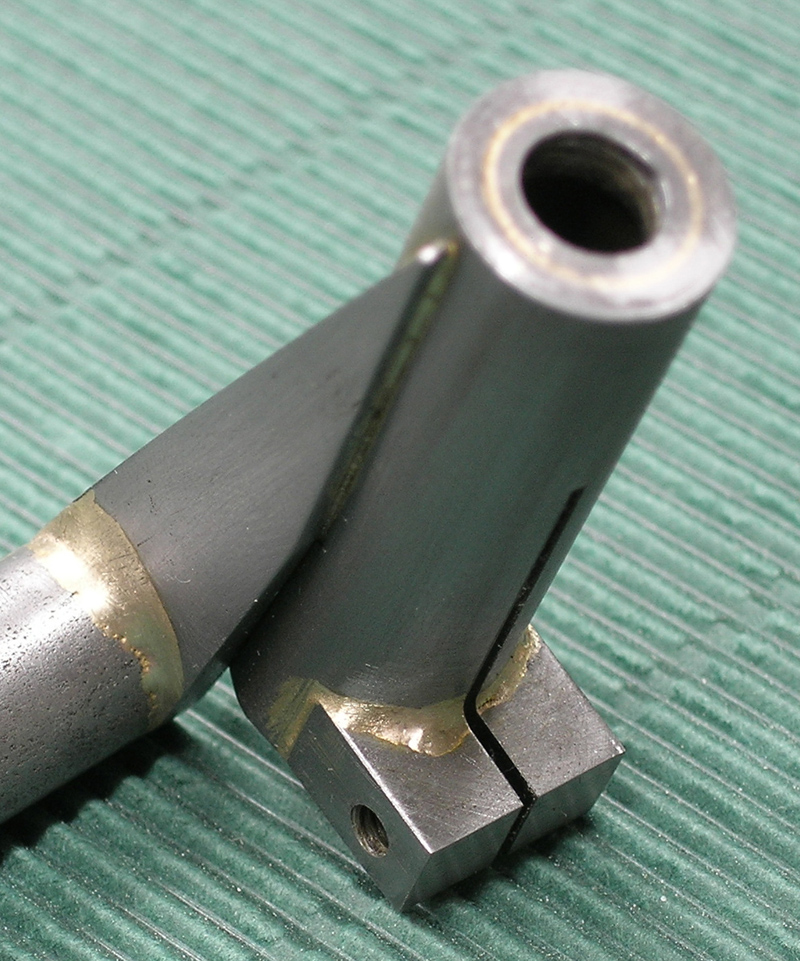
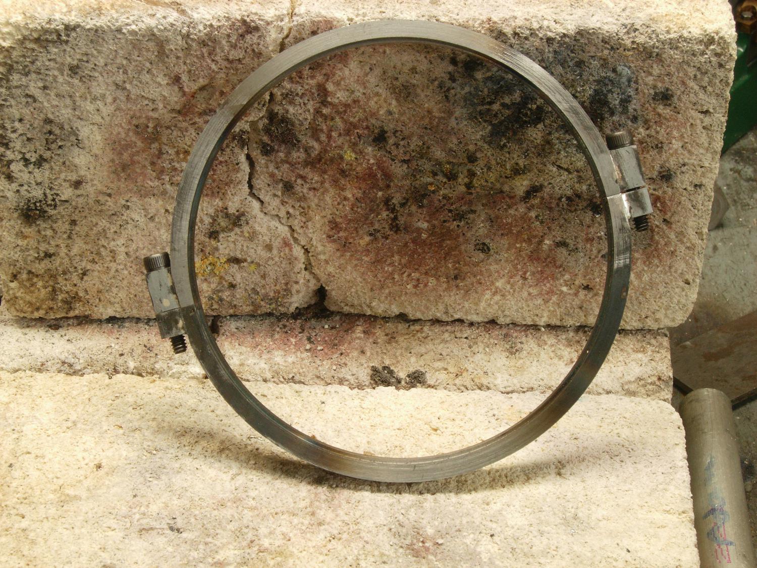
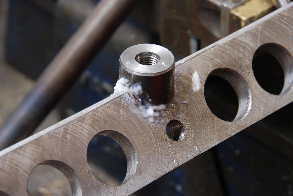
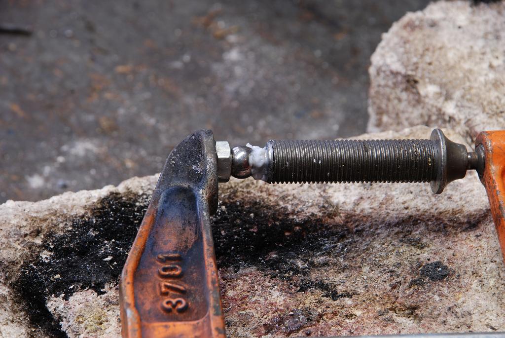
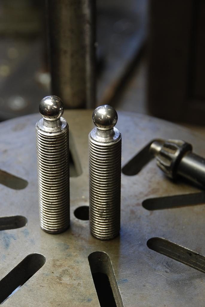
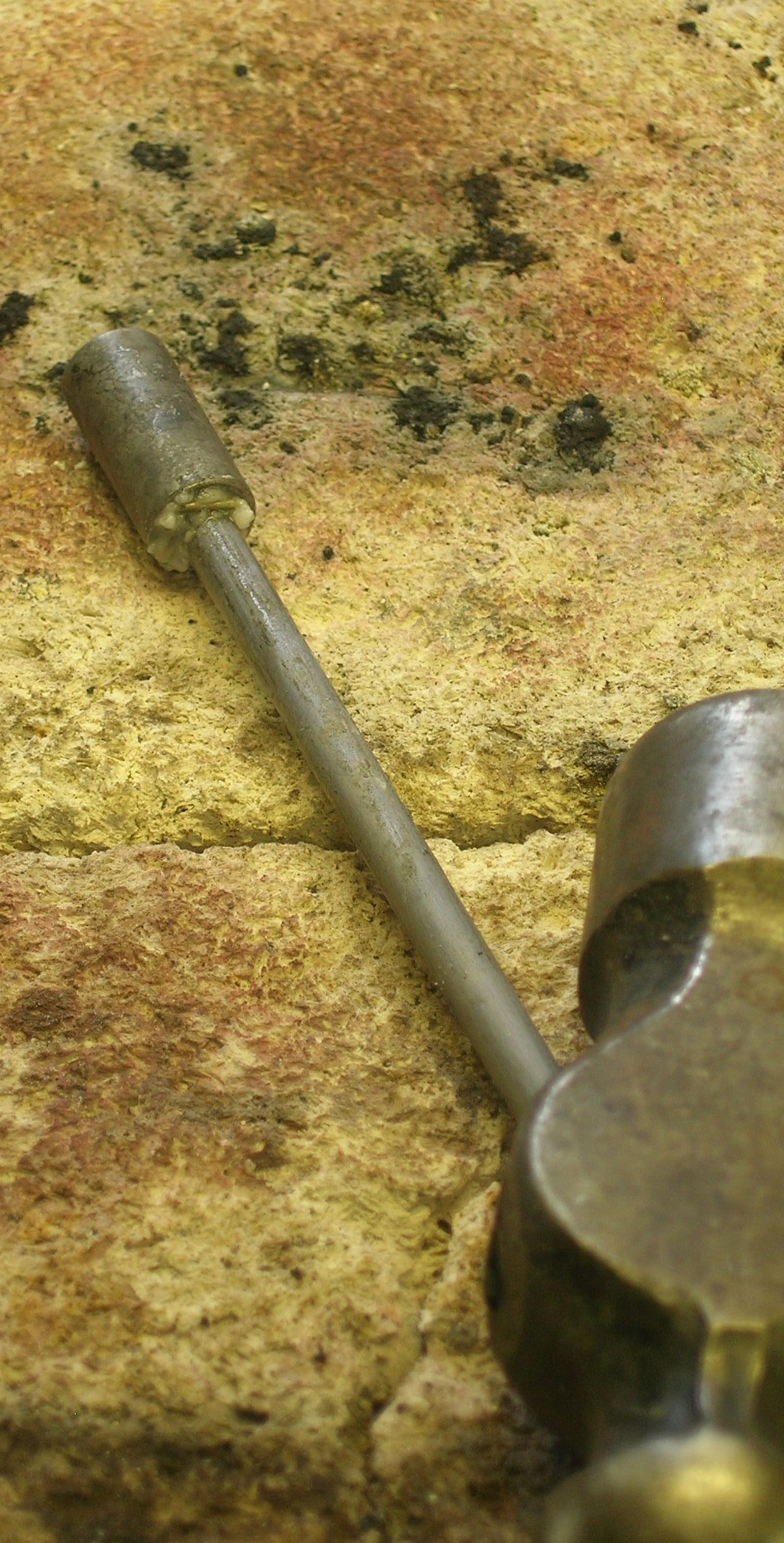
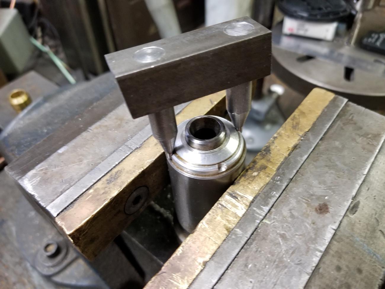
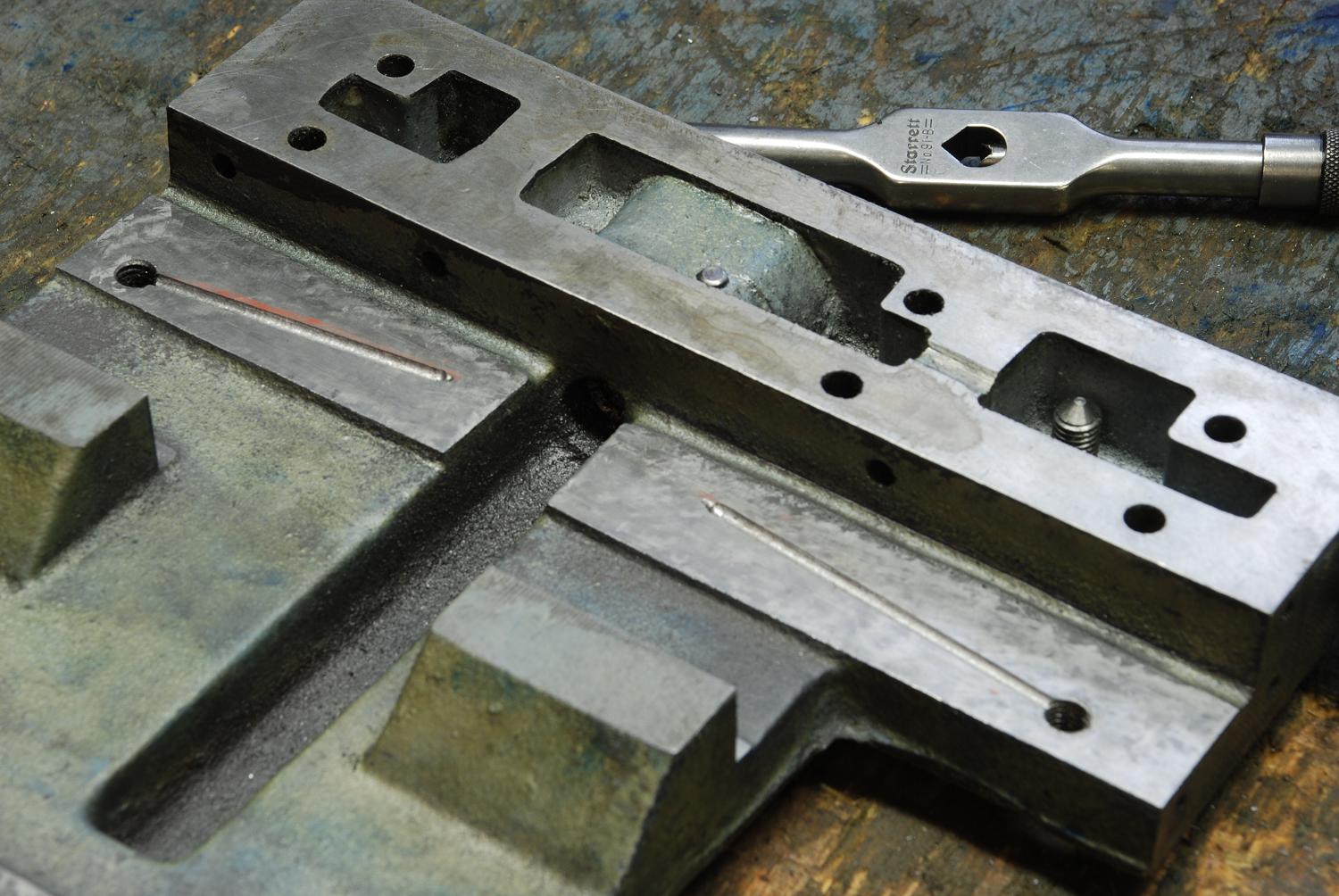
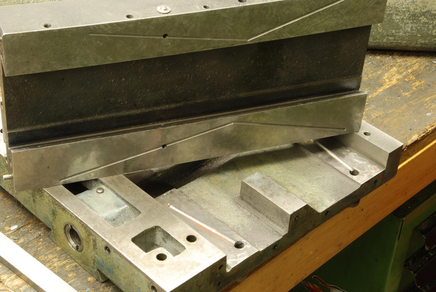
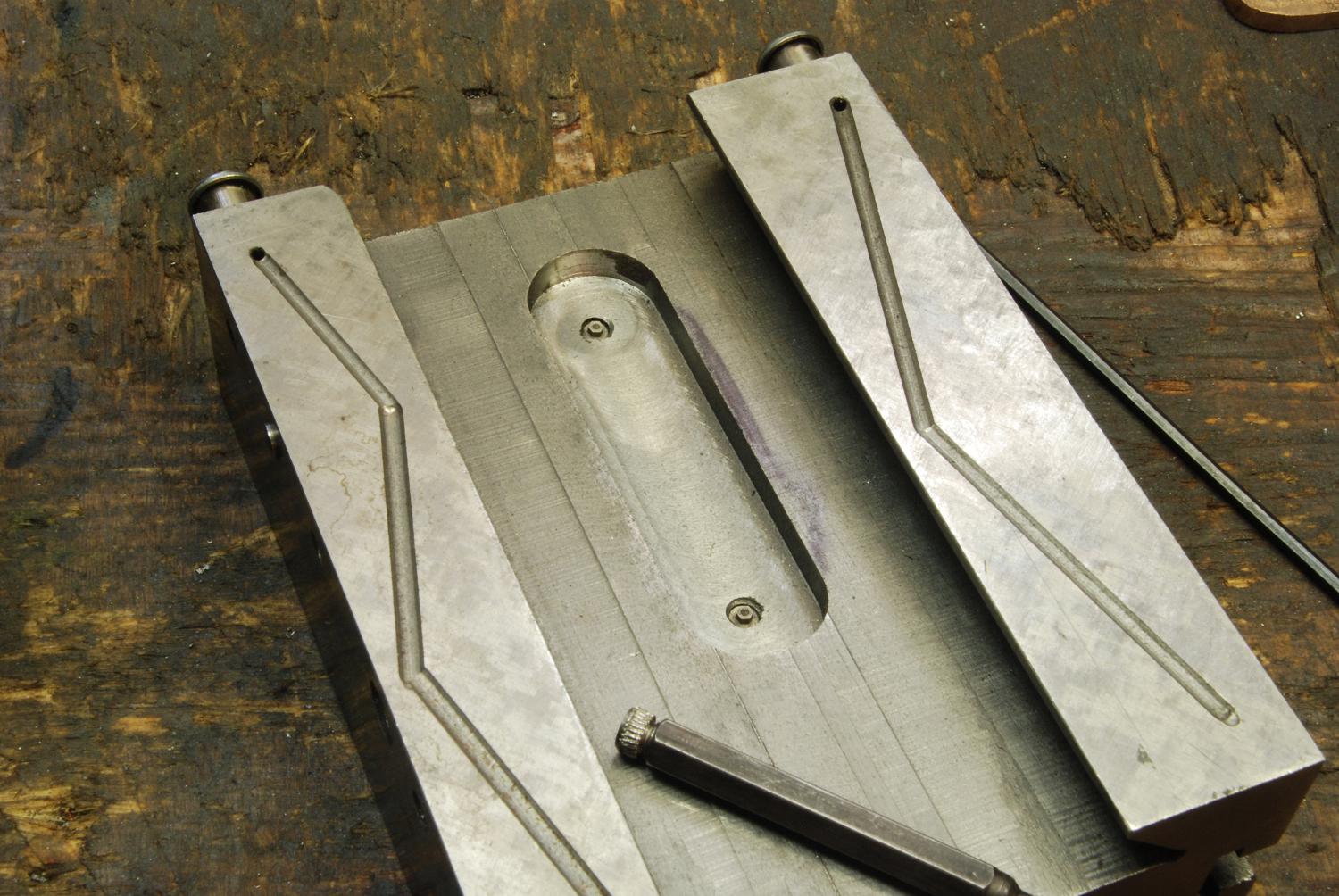
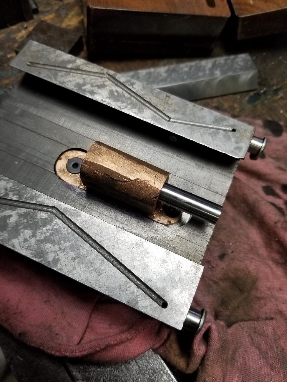
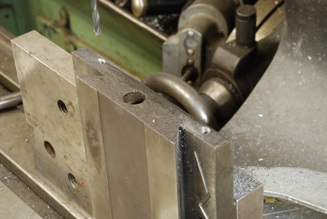
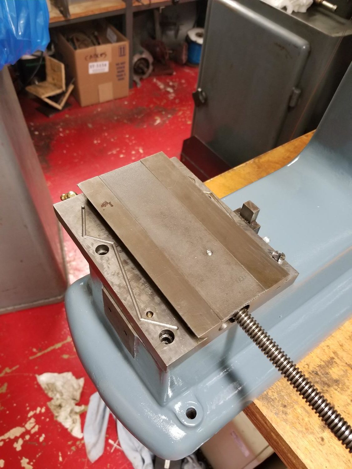
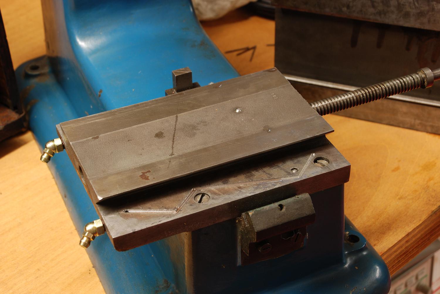
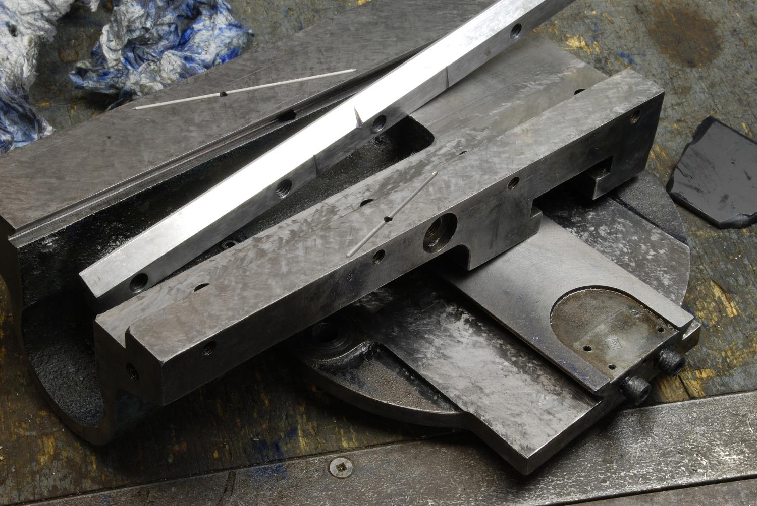
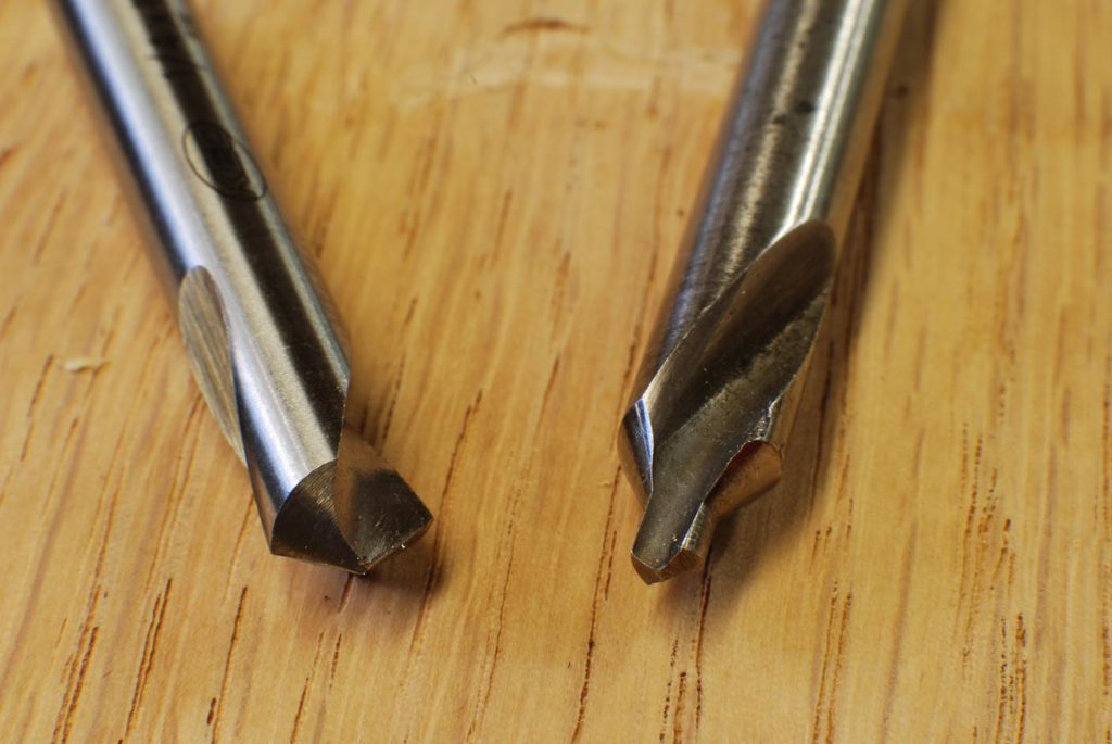
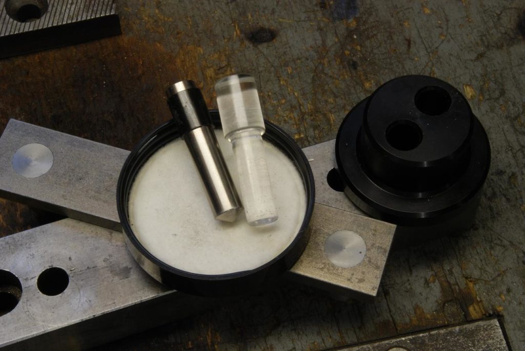
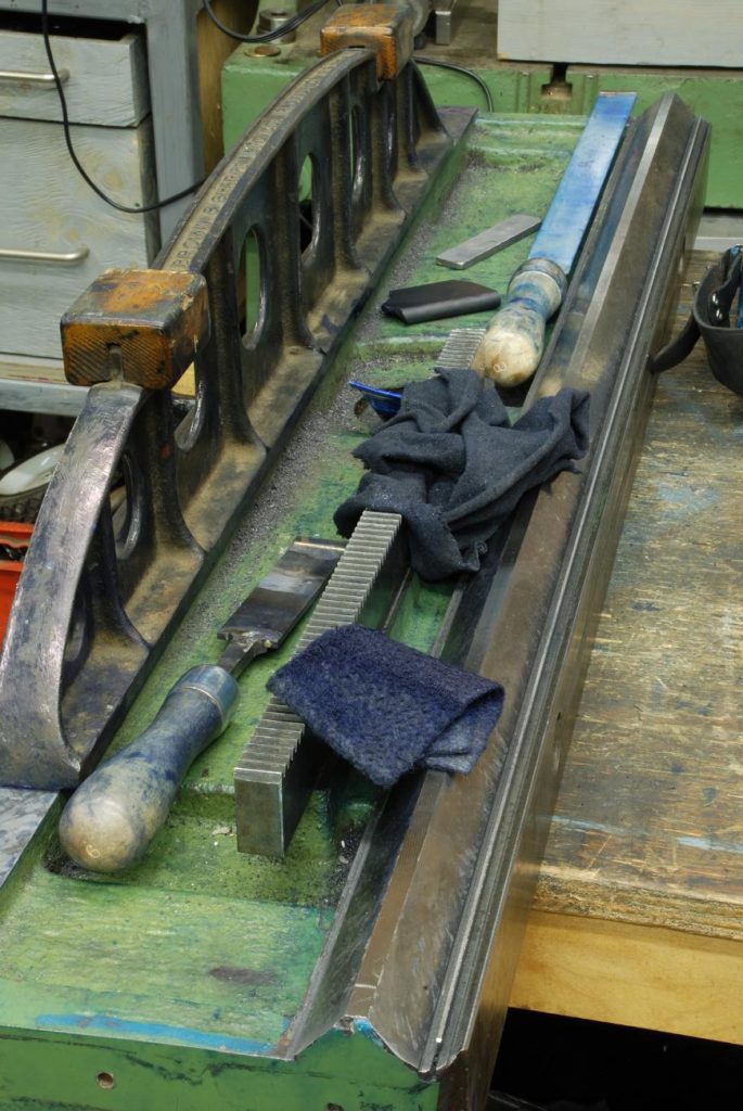
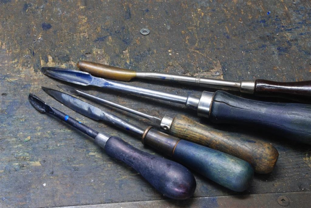
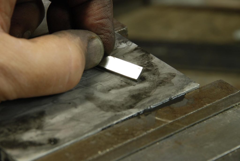
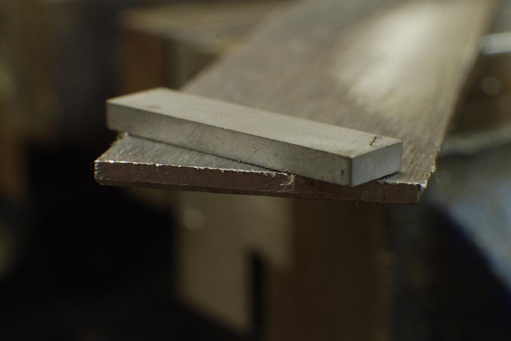
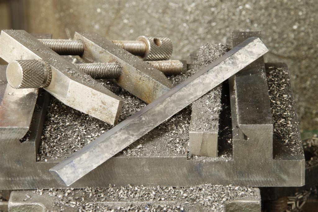
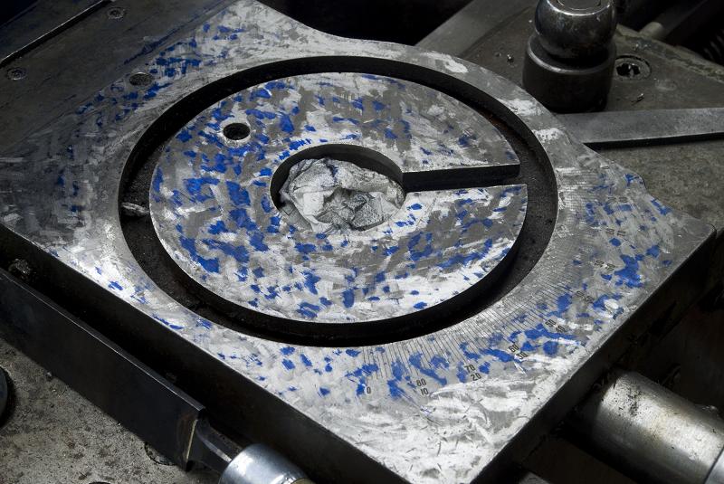
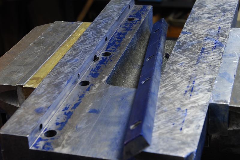
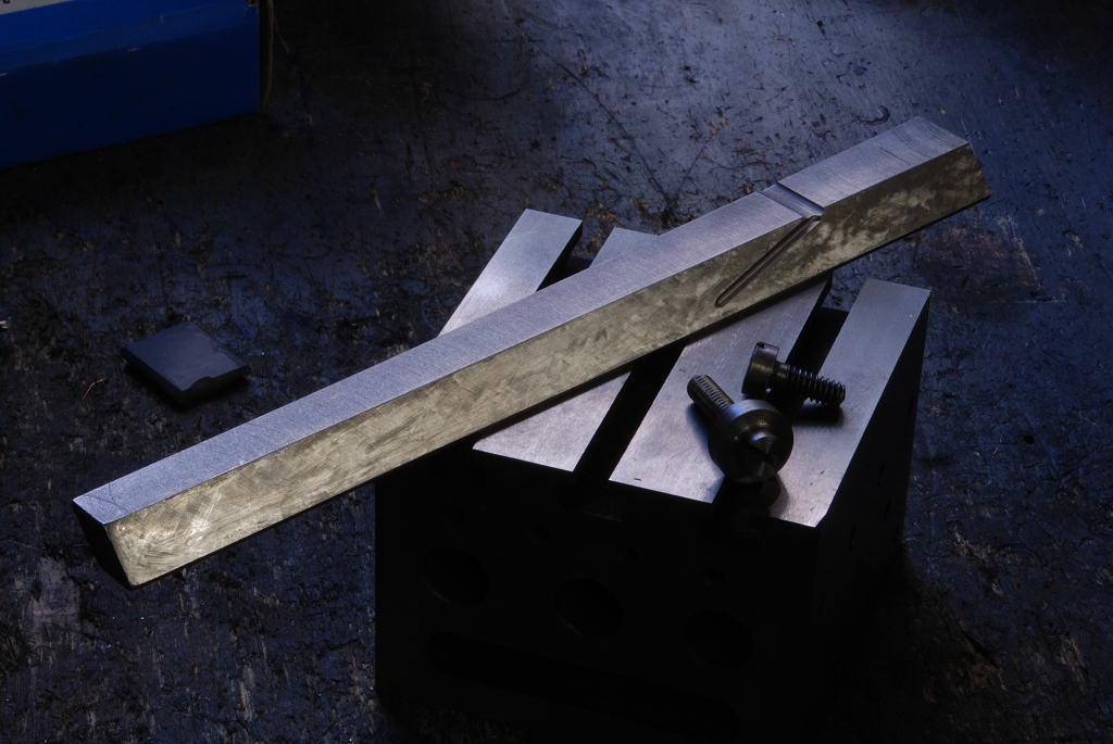
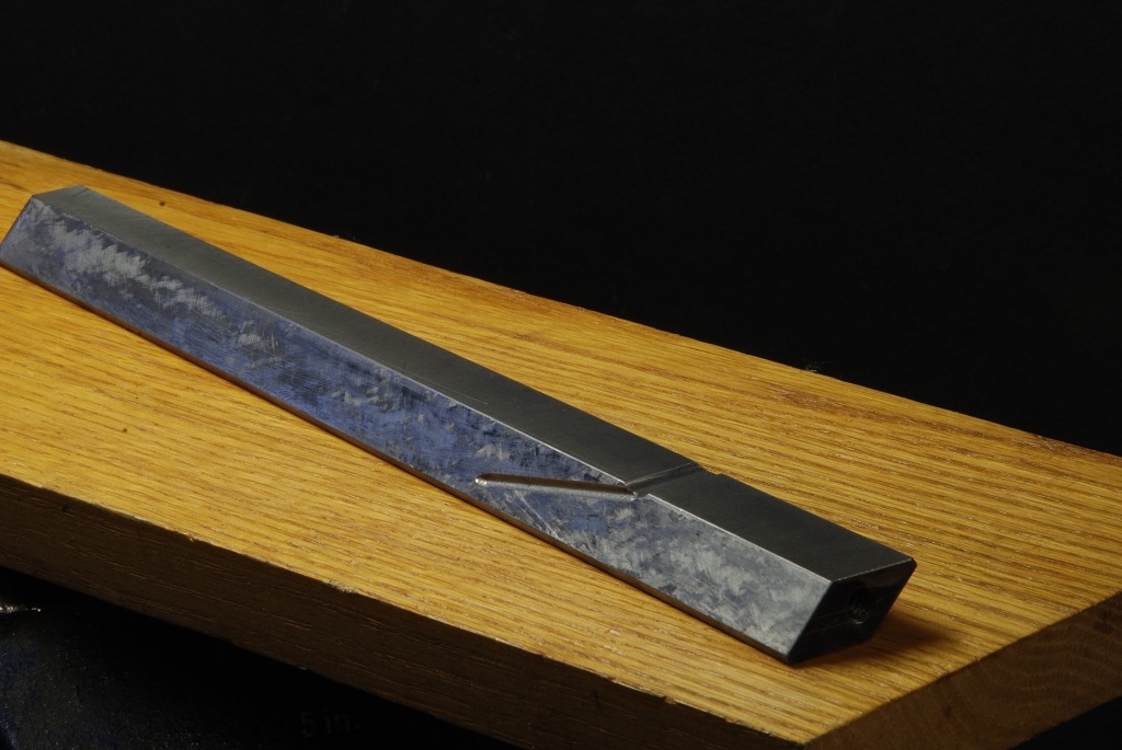
  Rule 2:  Make or buy the specialty wrench.  Numerous disassemblies, especially spindles, require you to make special shaped wrenches, spanners etc.  Examples shown in photos are for Levin spindles and the XLO spindle.  Its a royal pain to stop and have to make yet again another tool to get job, but its the only way to do proper job of it.

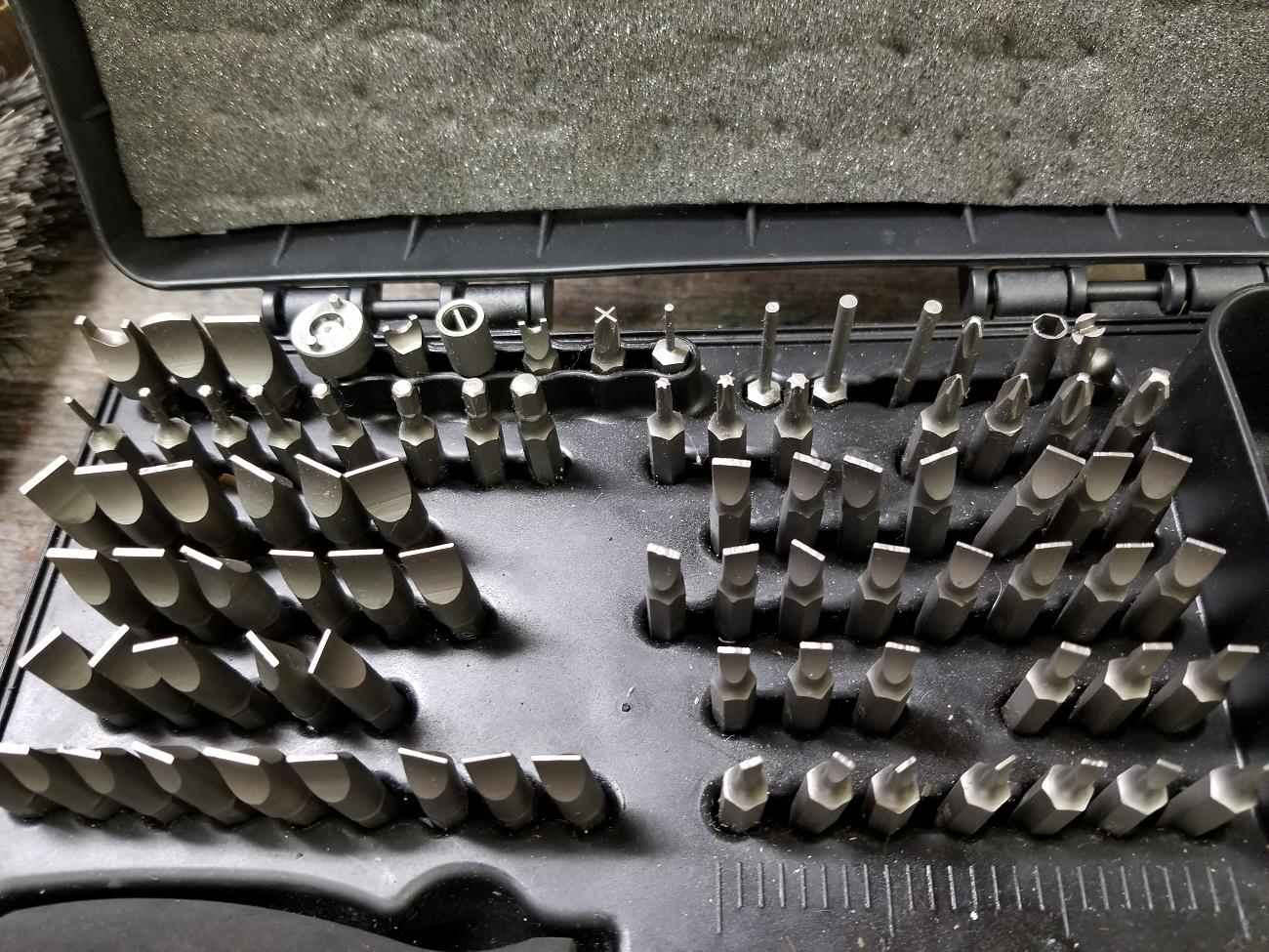
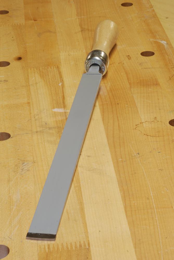
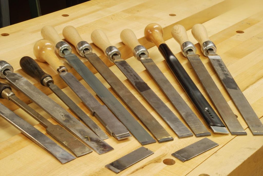
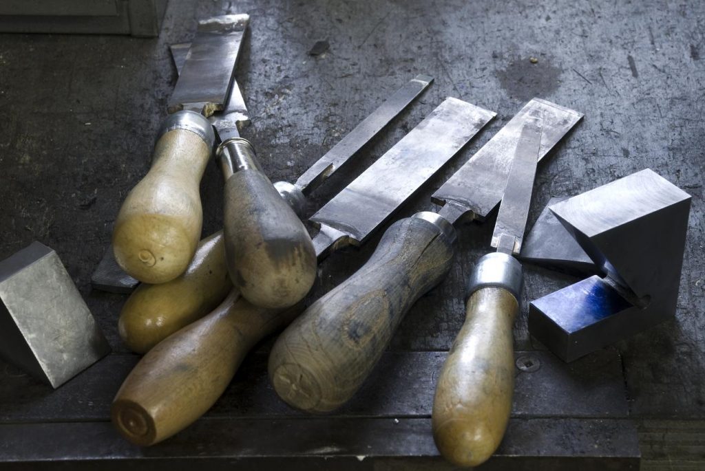
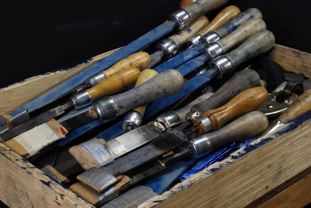
Rule 3.  Get a big set of hollow ground screw drives.  The gunsmiths have learned this and as far as I know the most complete are marketed to them.  The idea is to remove a slotted fastener, oh so common on older and antique machines (they are NOT vintage!), you a straight sided blade this is just shy of a tight fit in the slot.

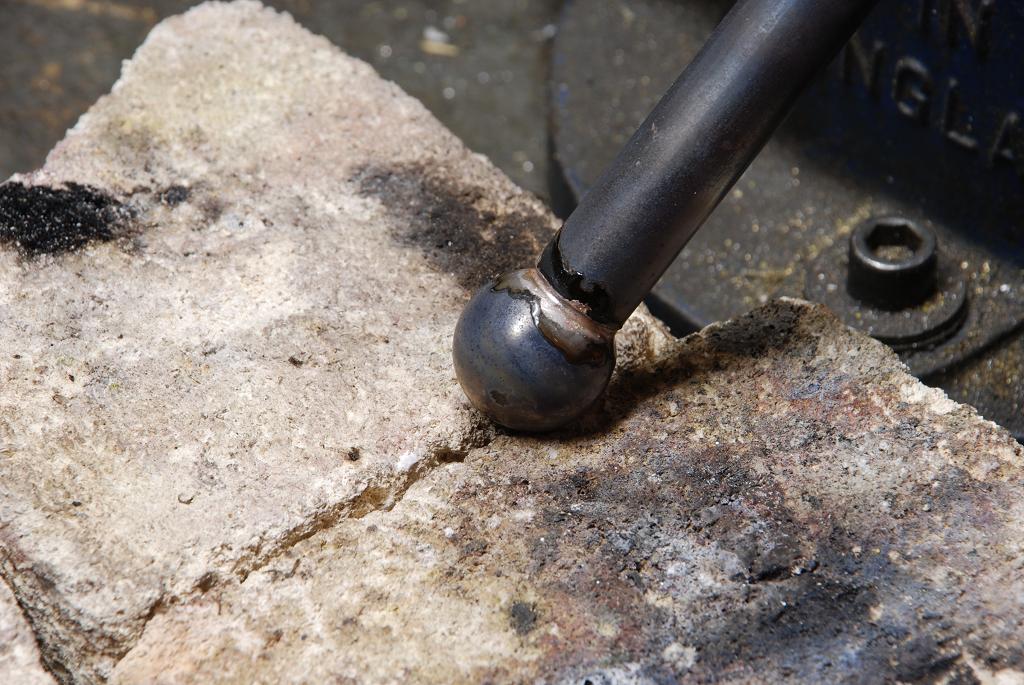
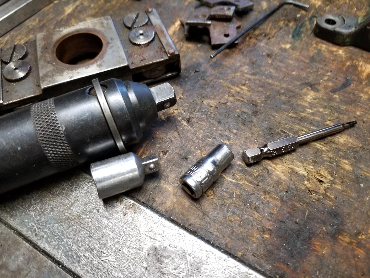
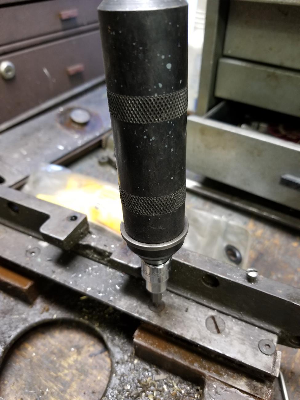
Rule 4:  Get a quality impact screwdriver.  Mine is a Klein and has been a good purchase.

Clean the faster and chose an appropriate end.  It comes with an adapter so you can use either hex bits or any 3/8 socket.  Place in faster and hit the end with a ball pien hammer.   When the hammer strikes, it forces the bit into the fastener but also creates a wee bit of torque.  This makes it close to impossible to strip the head.

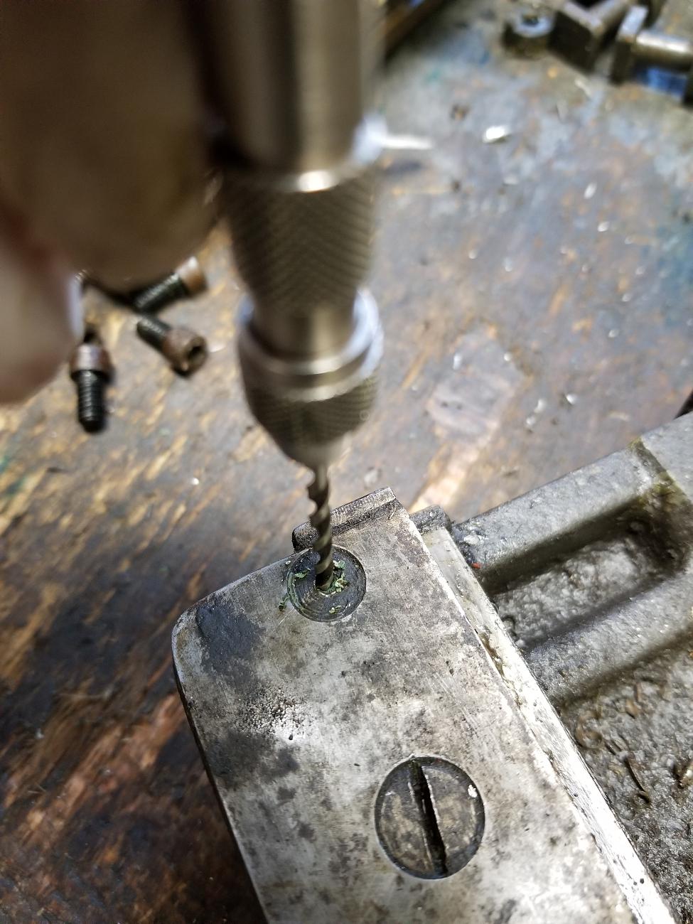
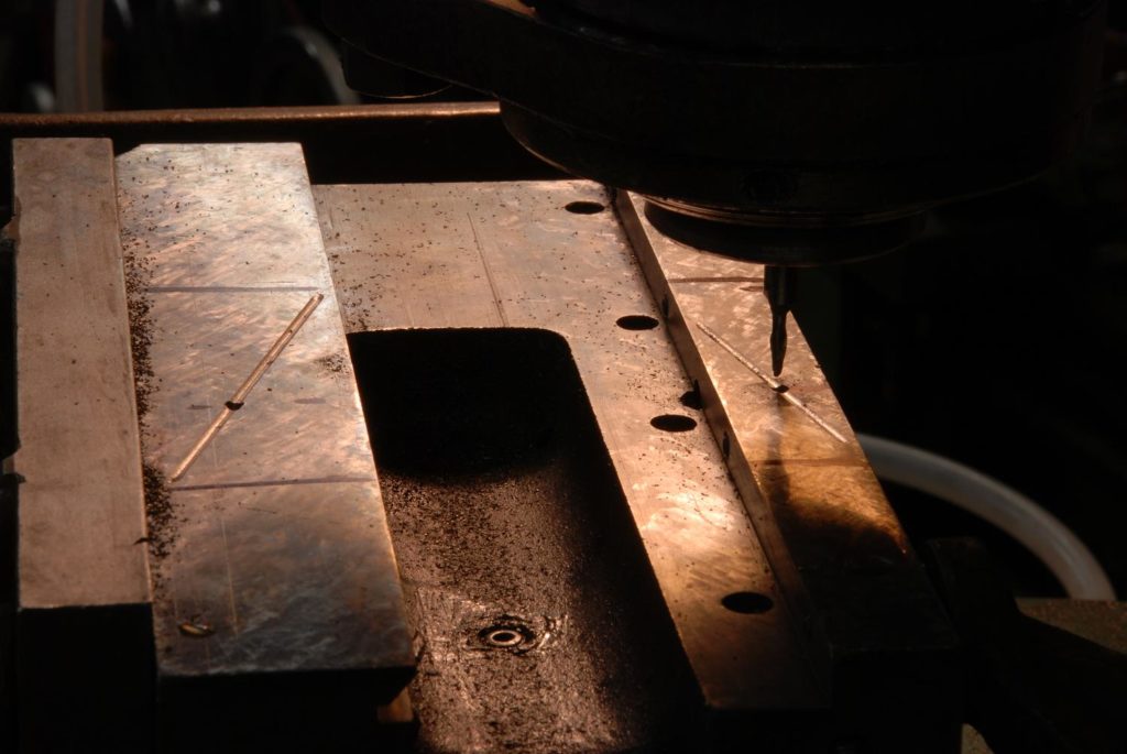
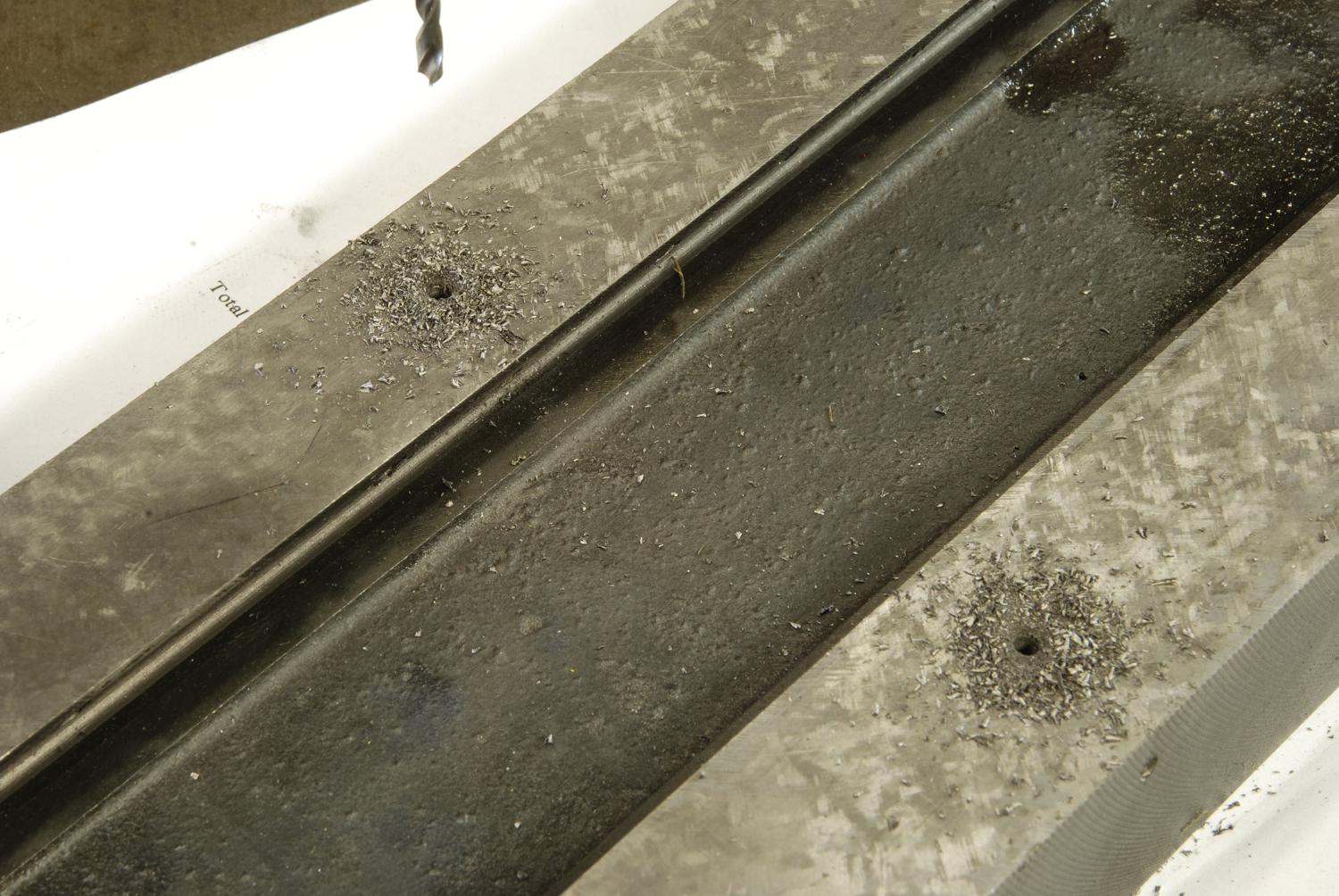
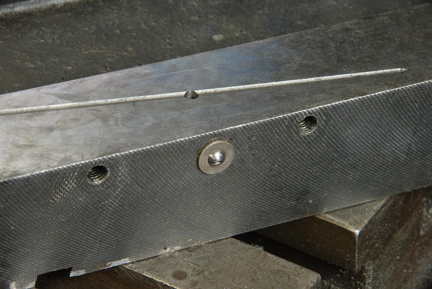
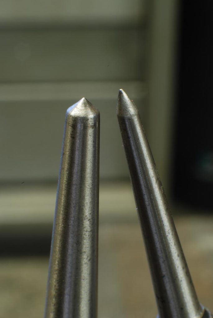
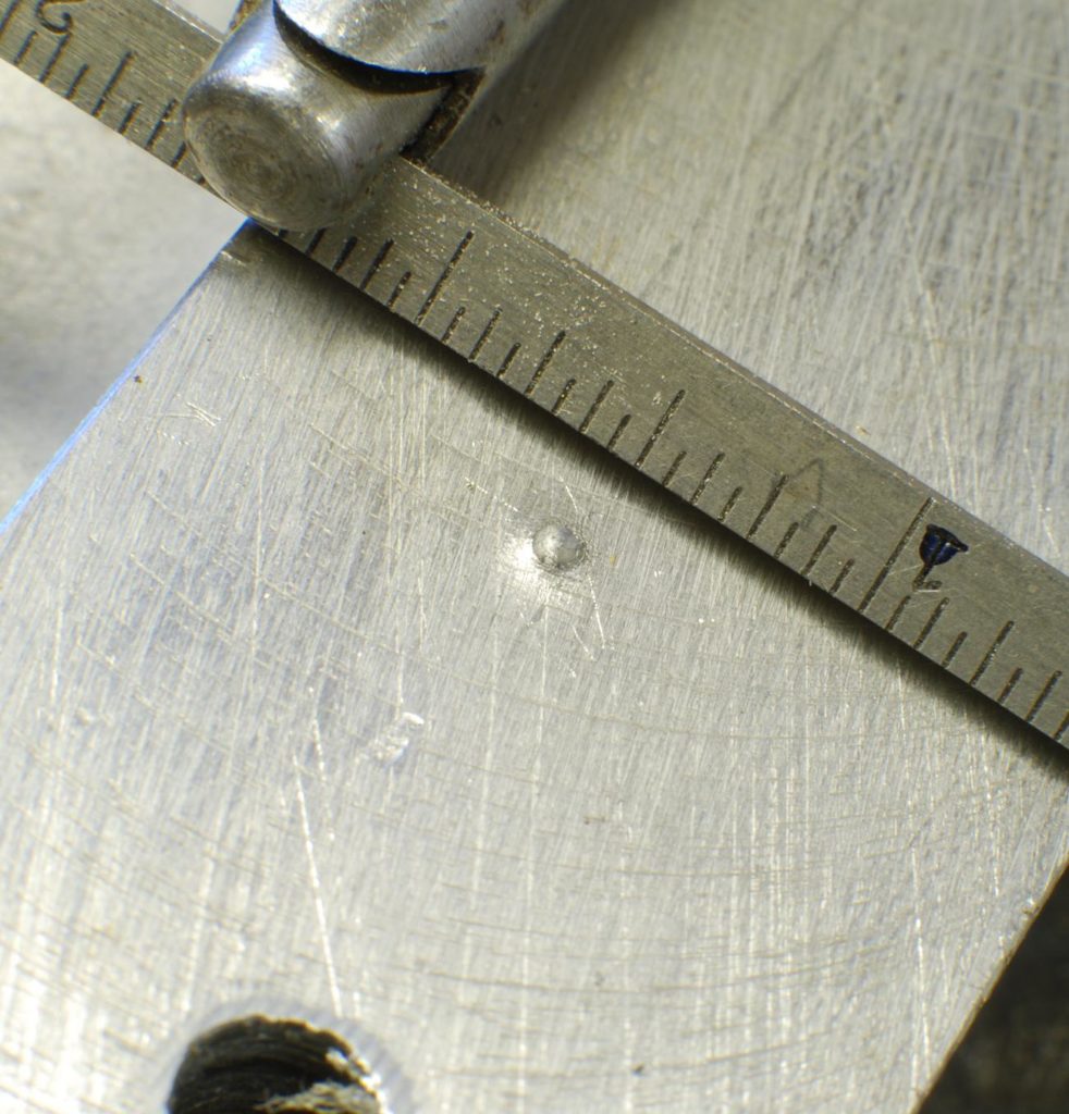
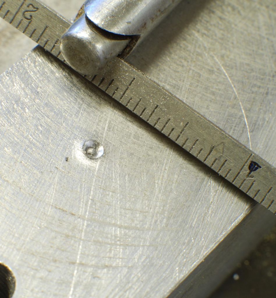
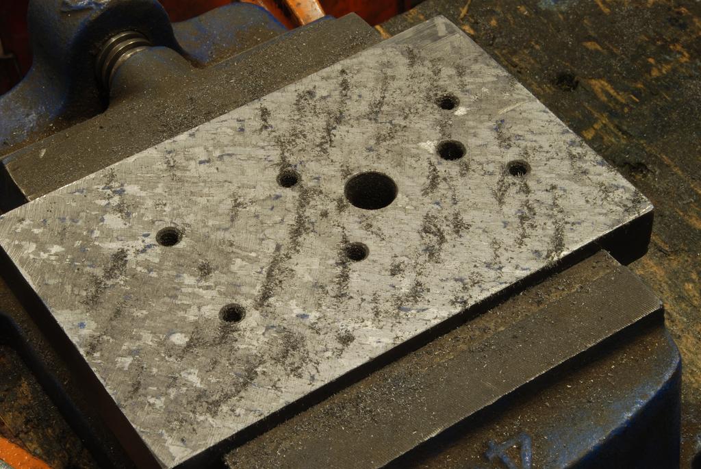
Rule 5:  spend some time studying pins before hammering away at their removal.  Most pins in machines are taper pins so of course only come out one way.  Carefully measure so only applying force to the small end

Rule 6:  here is the most important of all…..tap tap tap.  Whatever you are try to remove, if it doesn’t move with a modest amount of force, using many small taps or hits vs larger blows.  A bearing spindle retaining  that just wouldn’t budge with a destructive level of torque and or impact,. comes loose easy with 100 little taps…none of which are strong enough to wreck the nut.  This just works, use it and you’ll be amazed.


Machine Tool Oil Passages

Its disappointing how many otherwise high quality machine tool makers did not provide for oil passages – a way to get the much need oil into machine tool bearing surfaces.  But we can easily fix this!  I’ve reconditioned a few machines and always add such passages

A free form zig zag line cut with a ball end mill is all it takes.  Drill an access passage and install a fixture of your choice – cup or zerk for an oil gun

Starting a Hole

Yes, I know, such a basic topic, yet none of us were born knowing.  I’d bet there are more than few who’d consider themselves experienced.

Start with looking at a drill.  Its long and thin and easily flexed.  Its not pointed at the end but rather (with a typical grind) has a flat horizontal edged “chisel”.

Knurling

Annealing

Small Hole Drilling

In the machine shop, the 60-80 number drills are considered really small ….. but for the watchmaker, things are just getting started!  Holes down to a few thou diameter are done regularly.

A common refrain on small hole drilling is you have to spin the drill very fast at high rpm’s.  Utter nonsense, dispel the myth from your mind.

Fast helps mostly by making things go more quickly.  However the challenge to small hole drilling, which is fairly obvious, is how easily broken the delicate drills are.  (They are not drill bits, bits is what you find between the cushions on the couch, they are drills).

The two most important factors in the drill surviving, are concentrically of rotation and sensitivity of feed.  If you concentrate on addressing those two things, you can drill the smallest of holes regardless of RPM.

Concentricity usually requires high quality hardware.  (shots servo, dumore, electrical mechano, speeder

Scraping

A subject near and dear.

Many years ago, I had a kindly old British gentleman get me started with scraping.  As I tried to learn more I found the practice was held be some with perhaps a slight awe and lots of mystic.  Like it was some sort of black magic.

Baloney!  its a workshop technique and like any other can be taught and learned.   While it is fully capable of inducing back pain and tedium, it is not particularly difficult. 

Wanting to shed some light on the topic I ended up doing several projects and writing a 12 part article that ran for two years in Home Shop Machinist.  I am currently working on a follow up article, “Reconditioning a Lathe”

Where it does deserve some reverence and awe is in the levels of accuracy obtainable with simple hand tools.  It is as accurate as grinding and very often more so.

Here are a some images and notes on scraping to give a sense of it and perhaps whet an appetite

The basic tool is a scraper.  Here an assortment of ones I’ve made and a few commercial models.  The assortment includes carbide tipped scrapes and some forged file scrapers.  Carbide is much preferred, however does impose the need for more hardware for sharpening

I also like short handled versions.  I know the idea is get your body into the applied force, however a lot of the work I do is on small parts held in the vise on the bench – it isn’t just for machine tool reconditioning!

There are also bearing scrapers used for scraping the ID’s of plane bearings.  I’ve used them and they can be just the thing, however not relevant to machine tool reconditioning which is concerned with flat surfaces of ways and dovetails etc.

To make a carbide scraper, start with a small blank of carbide and lap the sides to a mirror finish using 9-10 micron diamond lapping compound.  Once made, you only sharpen by lapping the end.

After lapping, silver solder the carbide to the steel shank.

Sharpening is critical.   When you only have a 1/10,000″ depth of cut, the edge must be extremely fine else it will only bounce over the surface.

Here is a home made lapping machine made from an inexpensive grinder.  They heed negative with an included angle of about 92 or 93 degrees.  Any less, and they will dig in too much and exceed the available armstrong power to create a chip.  

This is actualy a key element if its accuracy:  the limited depth of cut available with the cutting tool geometry and human power.

Scraping Projects

Tooling

Scraping can used to create incredibly accurate tooling.   Here a V block and a cube are shown, each accurate to a tenth however you wish to measure them

Mini-mill Table

Done primarily as a demonstration of scraping dovetails, this table is now as precise and accurate as the best made Swiss machine.  First I had to make a reference flat, (commonly called a straight edge which always struck me as a poor name for it) to fit in the dovetails.  The reference flat must more acute than the dovetails; its only used to spot one surface at a time.  Cast iron MUST be used for the reference flat.  Its stable, easy to scrape and “print”s well (other materials don’t”

Starting with the table, one side made flat.   Then the horizontal ways are made flat, co-planer and parallel to the top

I’m just giving glimpses of the project, its complete coverage appears in the article.

The edge is made square to the table top and parallel to the T slots.

The angled portion of the dovetails have to parallel to the T slots is the table is a convenient reference accessible to both sides.

Lorem ipsum dolor sit amet, consectetur adipiscing elit. Ut elit tellus, luctus nec ullamcorper mattis, pulvinar dapibus leo.

Lathe Saddle, Cross slide and Compound

Working on getting the two horizontal way surfaces parallel.  This test, plus trial fitting of the cross slide (already scraped) were used.

Here’s the mating surface of the crors slide being scraped flat. 

The compound, cross slide and gibs

Lathe Beds

From an upcoming article, scraping projects include an instrument makers lathe, box way lathe and the common inverted V way lathe beds