Workshop Projects

Mandrel Tube Bender

two shiny neatly bent steam pipes are insalled on the triple explansion modle steam engine

Turning a BCA Jig Borer into a sinker EDM

A few decades ago Robert Langlois wrote a great series in Home Shop Machinist on making a sinker EDM.  For those not familiar, EDM stands for electrical discharge machine, a neat device that removes material by spark erosion.  The electrode is advanced to the work until its close enough to spark, then the electrode backs off, charges a capacitor then repeats.  The great advantage is it will go through anything conductive – hardened steel, carbide etc.  In this instance I had a broken a tap from hitting a hard spot created by a weld.

Several of Robert’s local club members built the EDM machines including the late Chris Bell.  A photo of his machine can be seen in the ordiginal article.  Mr Bell was a craftsman;  he did a beautiful job on the control/power supply unit.

Taking Mr. Bell’s EDM controller, I designed and made the mechanical parts to use my BCA mill as a sort of frame for the EDM machine.

Needed was a tank, a stepper motor feed mechanism and a head that could hold a collet and feed dielectric through it

The sparking is quite violent and needs to be done in a liquid to both flush away eroded particles and to contain the blast from the small explosion it creates (I suppose the instant boiling and hence expansion of small amounts of the dielectric)

My first attempt didn’t have enough fluid depth and stuff sprayed everywhere.  Then I tried a deeper plastercine well.  It worked for a bit but it would leak, the dielectric drain, and the same old problem.  What finally worked was a plastic container hot glue gunned to the work.

Commercial machines use  special fluids as dielectric and other things like Kerosene.  I wanted neither the cost, smell or risk of using something flammable and found plain old distilled, err, water out the dehumidifier, works very well.

The unit makes use of a lot of 3D printing and now looks a much better painted   I’ll have take some more photos….however here it is as I went through experimentation to success removing a broken tap.

The EDM was one of the reasons for making a new Z arrangement on this machine – so I’d have a T slot platform on which to bolt various implements of destruction such a spindle, edm, slotter head etc

I also put some videos up.  The plastic bags were to protect adjacent machines until I learned to control the splashing with a proper dielectric depth.  Also things need to be bolted down.  Surprisingly there is enough forces generated to moves the work over the course of a burn which causes failure as the electrode starts making side contact in the hole

using a container to form a well

The Cut Knurling Tool

Being able to cut knurls is, in the world of knurling, liking riding in Roller.

Sharp, crips knurls are cut in one pass at speed with almost negligible force against the lathe spindle or the cross feed.

The knurl wheel axles ride in ball bearings.  The angle the knurl makes relative to the work needs adjusting for different diameters and there is also a height adjustment for convenient tracking

This tool led to a detailed build article in Home Shop Machinist magazine

mw diy cut knurling tool for lathe

The Finger Brake


Another item that was done as an article in Home Shop Machinist.  The turnbuckle required a left hand thread, I think was one of my first times making a tap – it worked well enough!

Custom Counterbores


A principle of craft is building blocks – developing skills that let you do more and more. An excellent example is making unusual tools when needed.

Here is a simple example, a small counterbore. In this case, I need a counterbore than could be detached from its shaft so it could work on the inaccessible area – to spotface the underside of a hole in a casting that was only accessible from one direction

Oil Gun

Machine tools almost universally require oil, preferably way oil, on the bearing surfaces of their ways.  Its very common to see ‘zerck’ for administration of said oil. (and a classic terrible newbie mistake to apply grease, how I first learned to take a mill apart lol)

Unfortunately decent oil guns that fit the zerk fitting  are about non existent, so you make one.  Essentially all you are doing is creating a sealed end.  These grease guns are horrible made so you can get some leaking at the business end, but at least you can oil the machines

Mini mill table

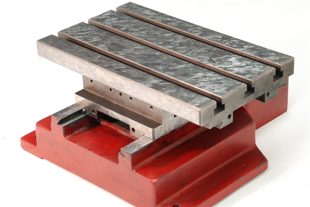
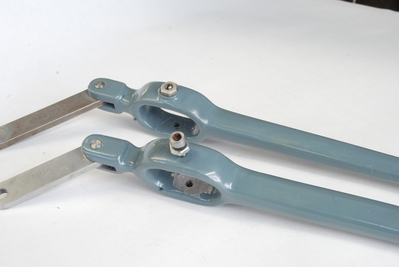
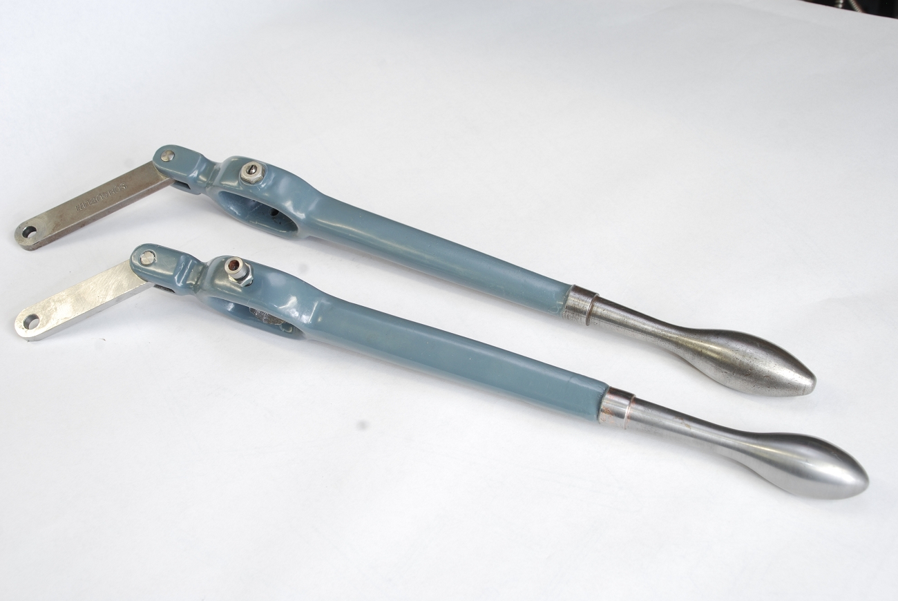
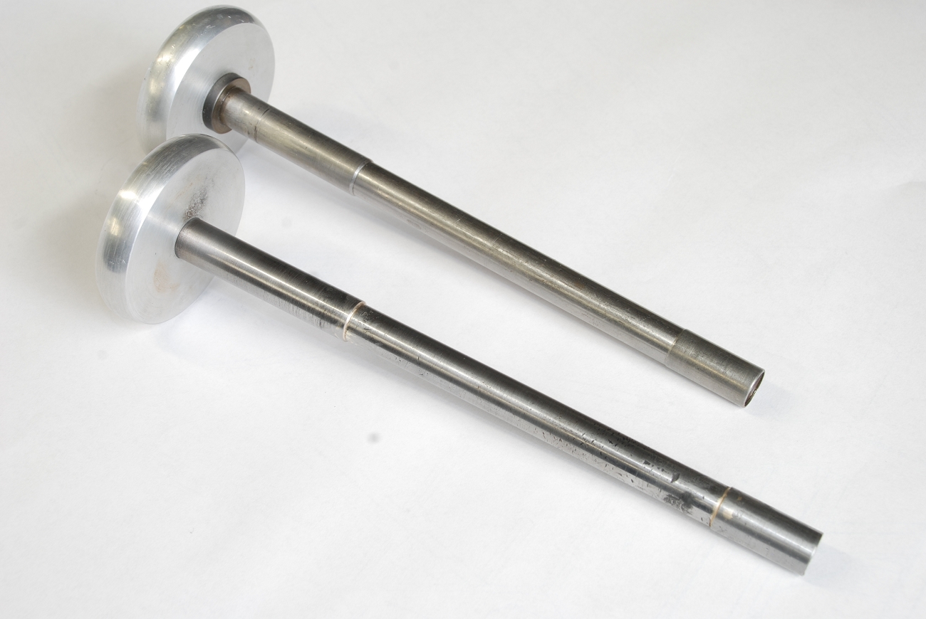
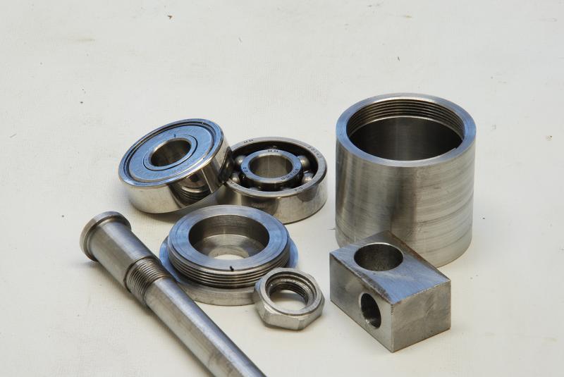
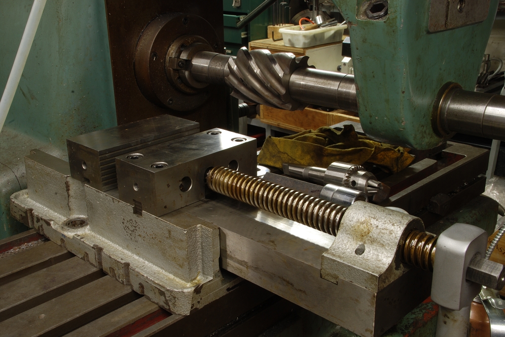
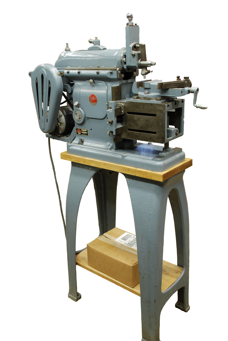
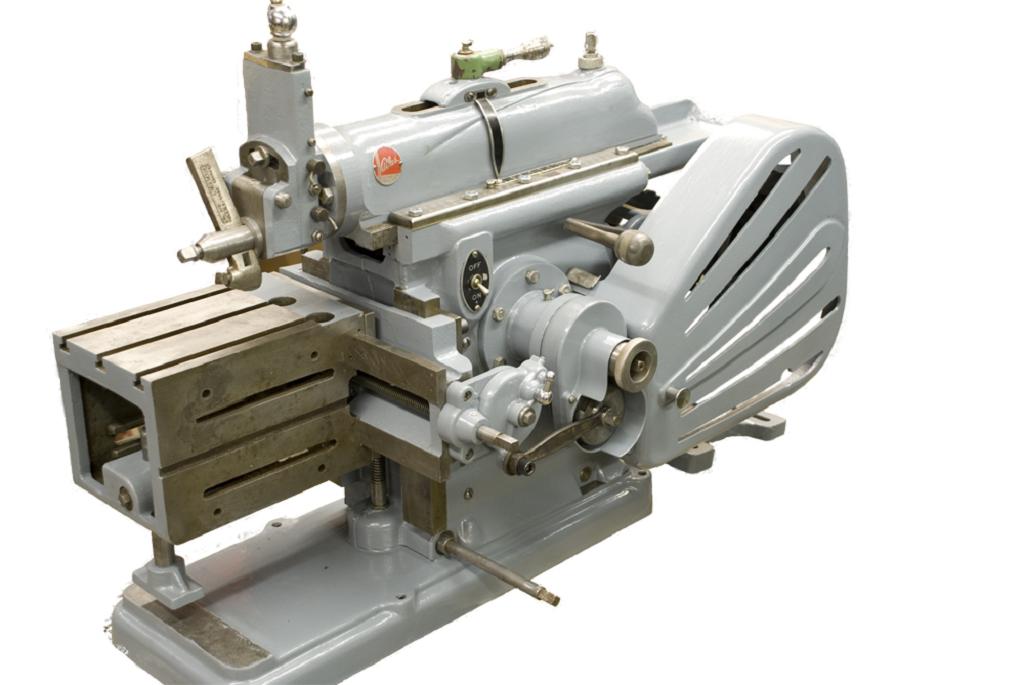
Some years ago I wrote a long series (ran for two years) in Home Shop Machinist on scraping.   Wanting to included to a dovetail project from start to finish, I spotted a set of mini mill castings for sale online. 

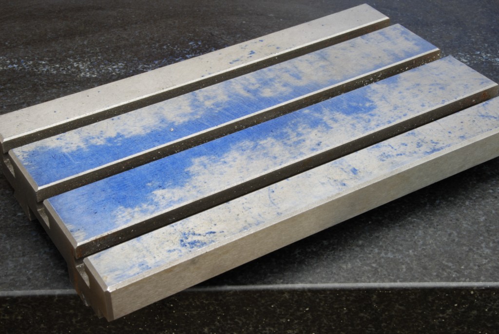
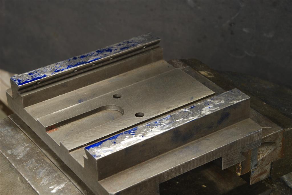
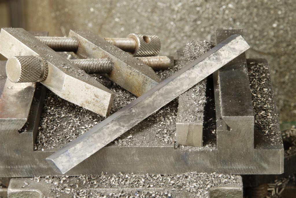
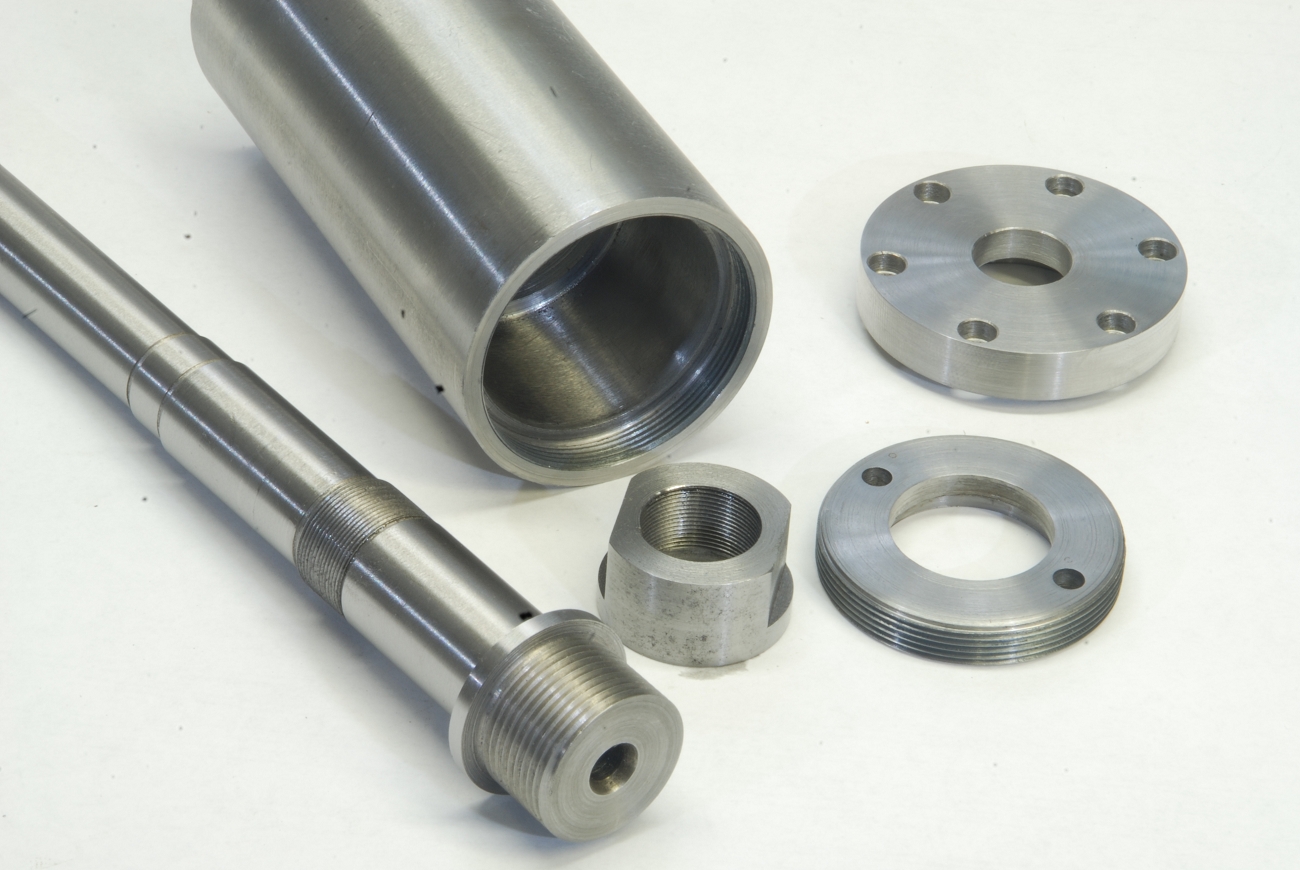
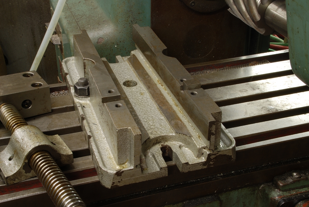
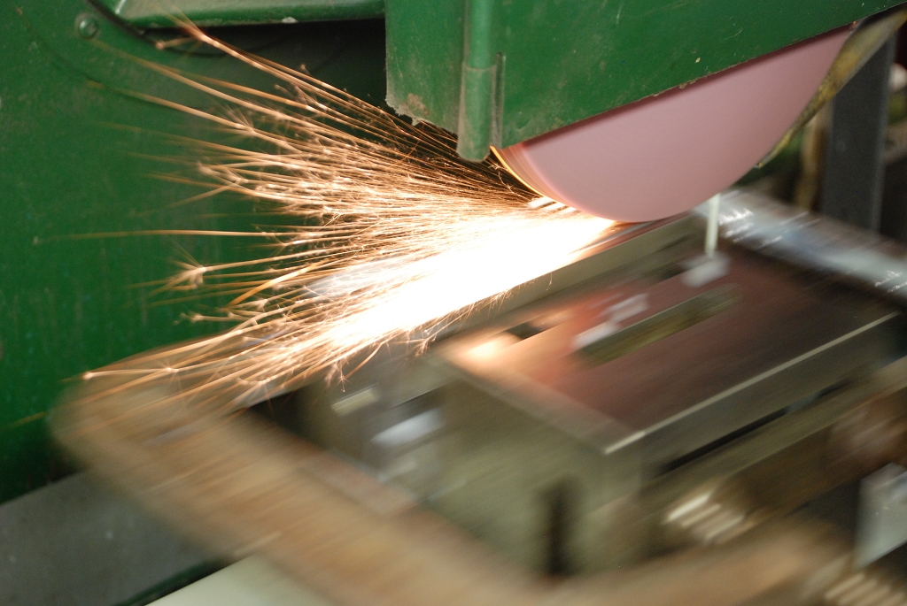
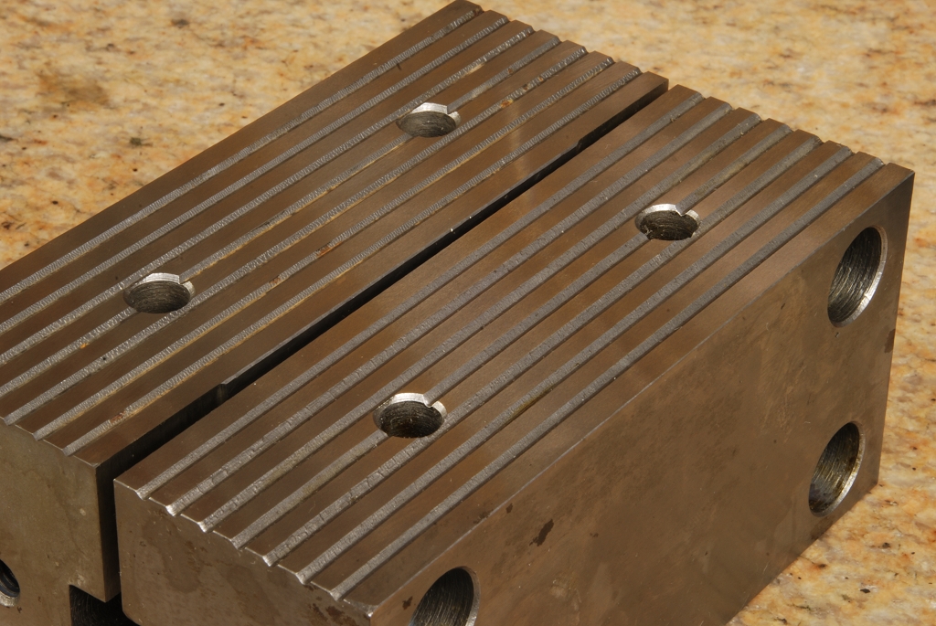
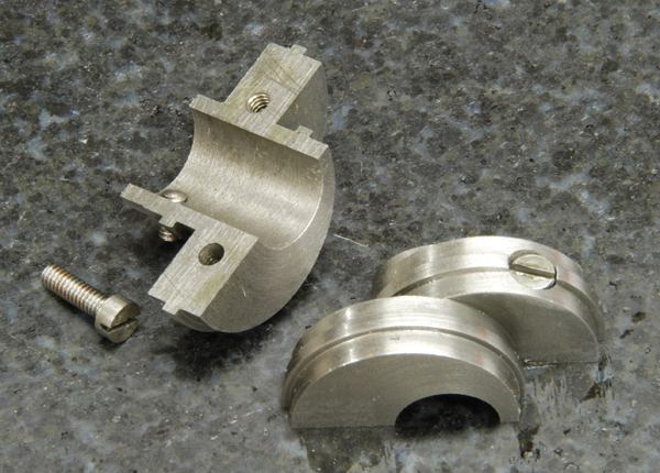
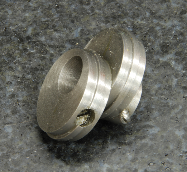
The quality of the fit and finish of these supposedly finished parts is atrocious.  It was so bad, surfaces that didn’t touch were ground so they looked nice where as others that were bearing surface were rough milled.  The good news is the casting material itself was ok, no voids or hard spots encountered.  I didn’t check it beyond that; the material is likely not very high quality, however we can mitigate that with lots of lubrication.
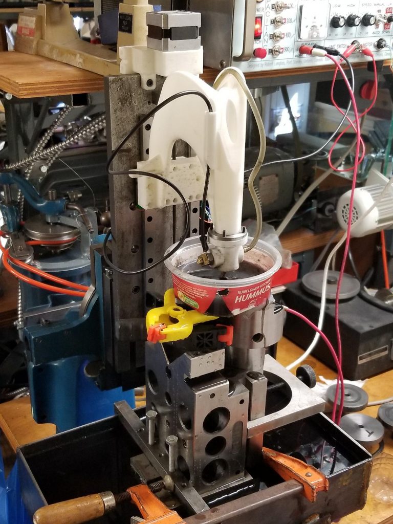
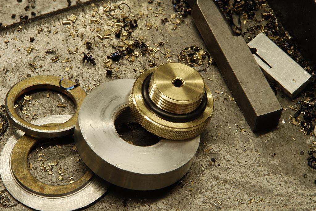
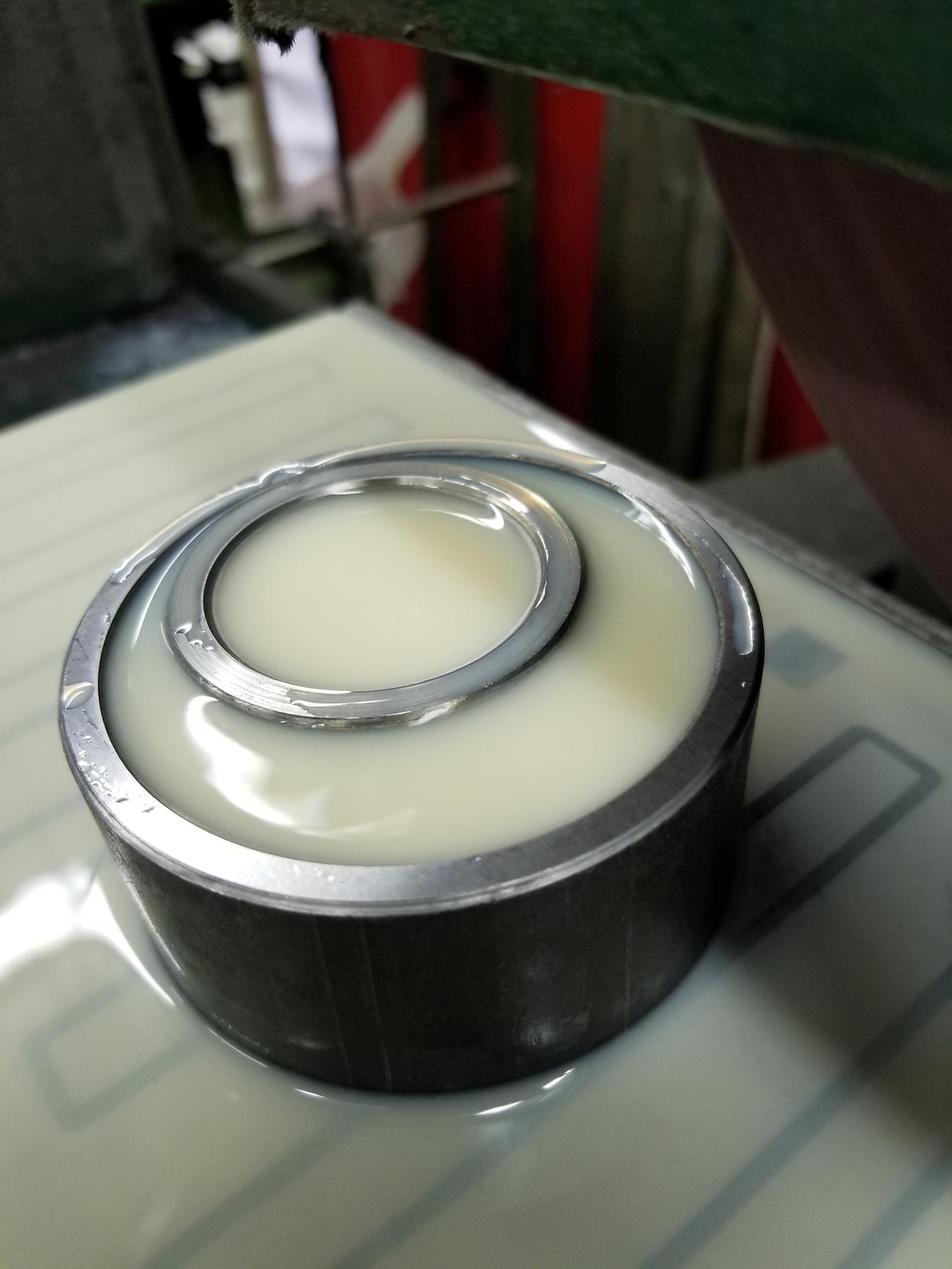
Lapping Compound.
There is a “thing” I think commonly done to “fix” some of these mechanical atrocities:  the indiscriminate adding of abrasive to supposedly “lap” the parts into a better or perfect condition.
 
I’m going to the take firm stand that this is just wrong and is done out of ignorance.   I don’t say ignornace with any malice, the word means a lack of knowledge.  There is no shame in being ignorant, stays so is a another matter :).  I’ll to explain why it shouldn’t be done:
 
1) It isn’t really lapping.  Lapping of flat items (cylindrical is a bit different) is a precision operation involving a very flat lap that is charged (abrasive is embedded in its surface).  Add grit into, what are supposed to be precision surfaces, isn’t lapping as there is no lap.
 
2) The removal of material is not controlled.  If you are trying to make the surfaces of parts fit together well, you must remove material from high spots.  Randomly removing material is not going to improve the the geometry (i.e. flatness) or fit. 
 
3) When you lap, you embed the abrasive in a tool (the lap) and then use it (the lap) as a cutting tool.  Normal practice is that the lap is softer than the work piece and there isn’t lots of loose abrasive present.  When putting lapping compound between two bearing surfaces of the same material (and same hardness), the abrasive compound will get embedded in these surfaces.  This means the two bearing surfaces become cutting tools, each cutting and will be wearing away at its mate as long as the machine is used
 

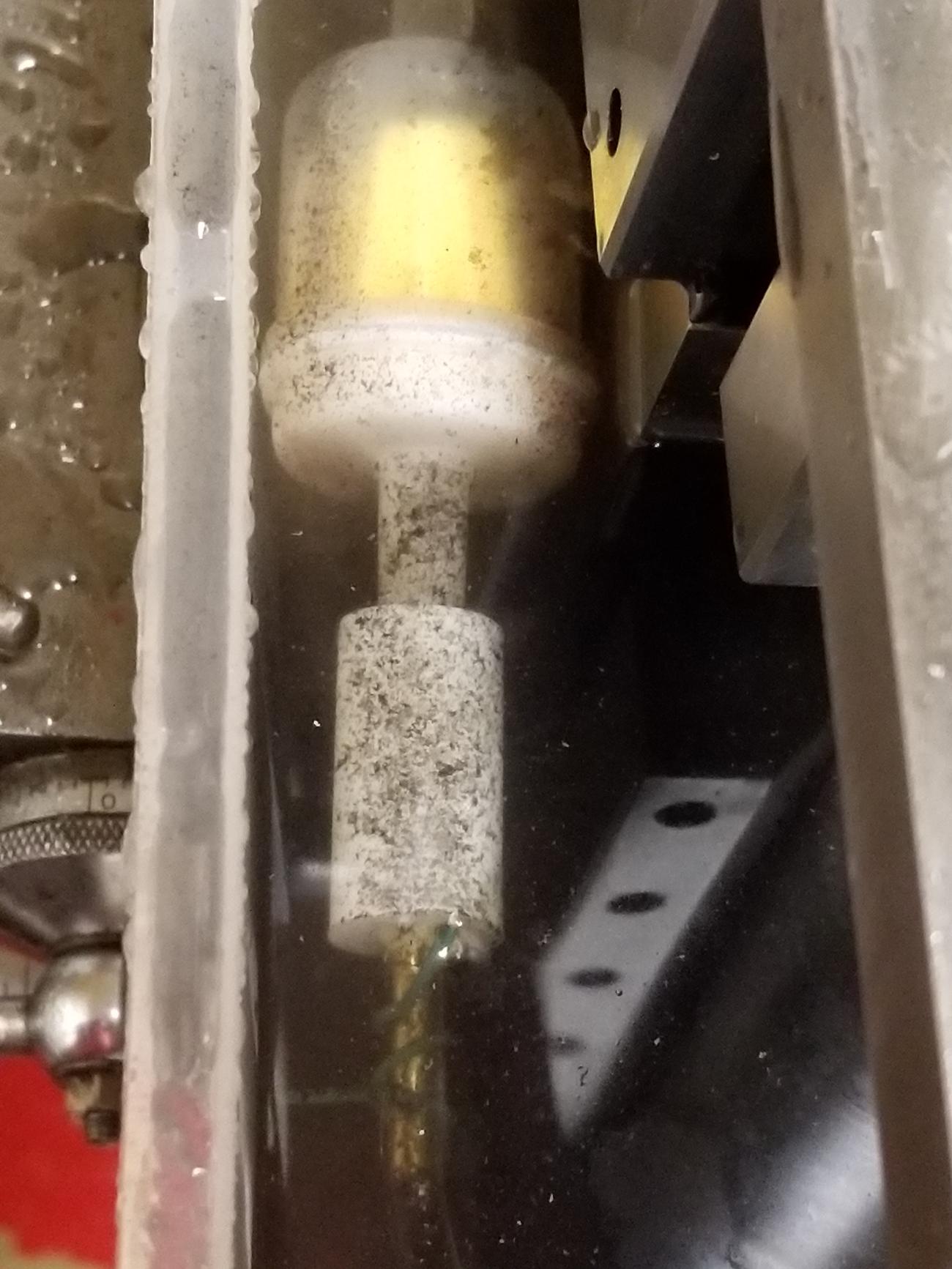
Charging and use of a lap is kind of a neat process in that surface of the lap is never touched and remains like new…only the embedded grains of the abrasive make contact with the work

 
4)  The argument sometimes proffered in defense is that “it makes its operation so smooth”.    That may be the case however smoothness has been achieved by created excessive slop.   Suppose you have a .998″ pin in a 1″ bore and the surfaces have a enough variation that there are some rough spots.  Would abrading things away until you had smooth .997″ pin in 1.003″ bell mouthed hole improve things?   Not where machine tools are concerned….where the geometry and fit of bearing surfaces determines the accuracy and rigidity of the machine.  Adding slop radically degrades the machine.
 
What do to?
 
There is no free lunch.  If want a machine to perform well, the bearing surfaces have to be spot on.  This means either spending a lot to acquire high quality new(ish) machines in first place, or you learn how to scrape.  Scraping lets you achieve the highest levels of accuracy rivaling or perhaps even surpassing that of the best machine tool manufacturers.
 
If someone had a mess of a tool on their hands and wasn’t able to get their heads around scraping (its really not that hard), the worst of the surfaces stalactites and stalagmites could be knocked of use small Arkansas slips stones.  This won’t improve the machine the way scraping will, but it might make it smoother.
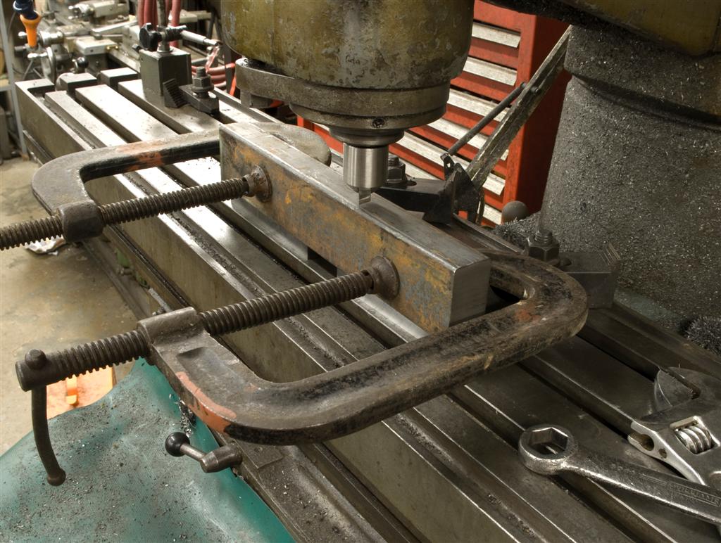
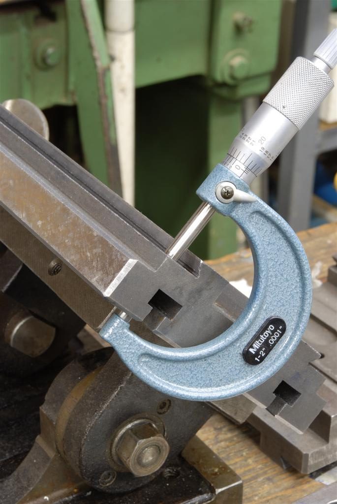
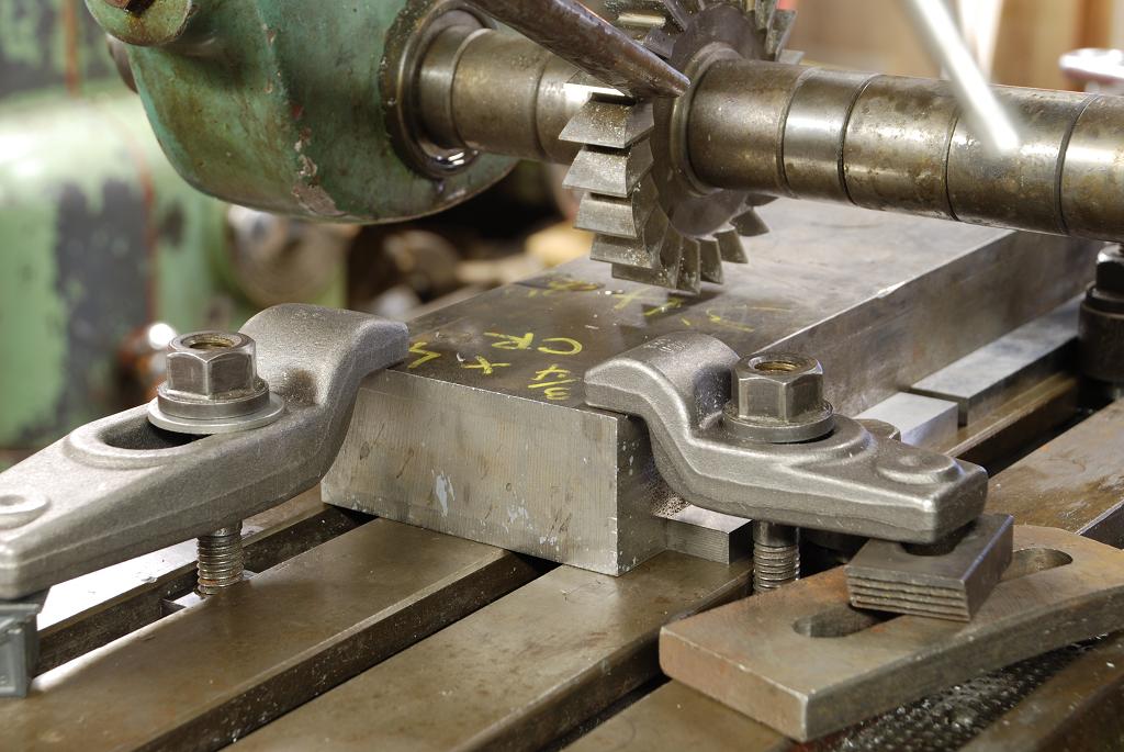
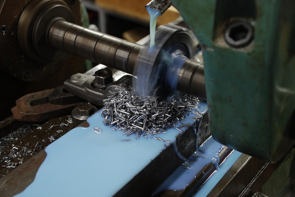
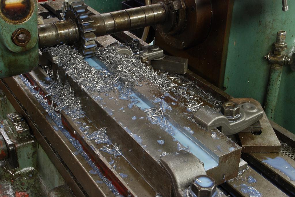
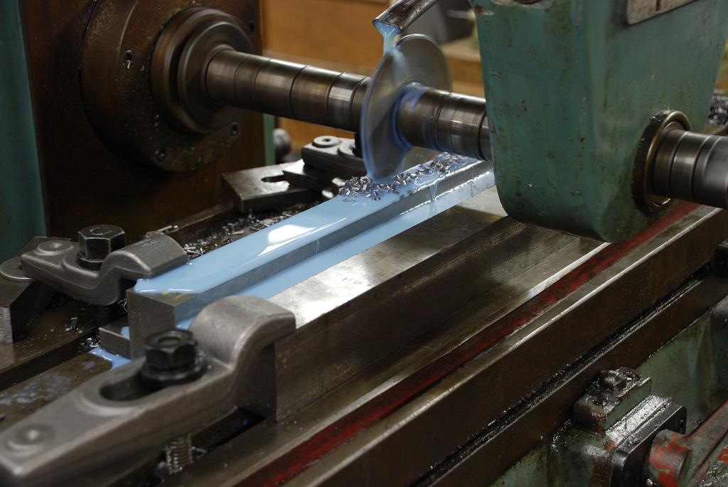
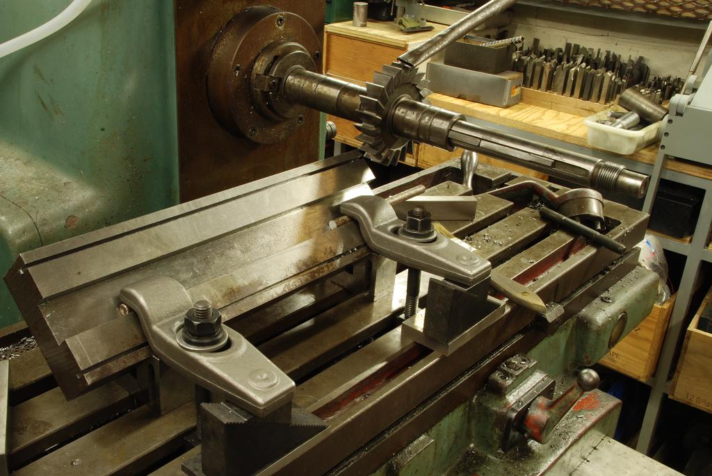
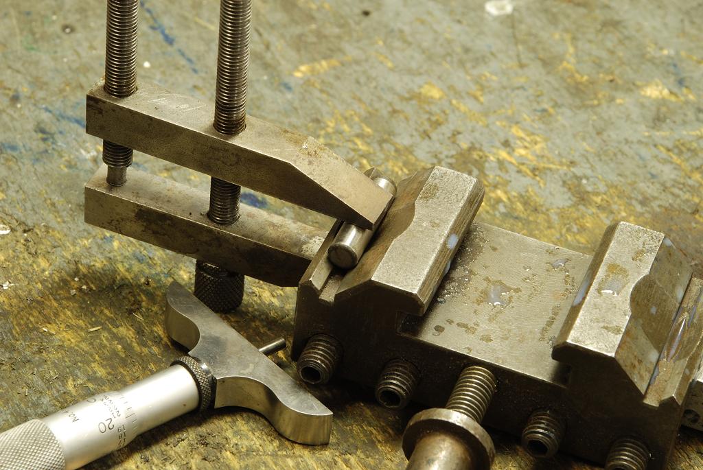
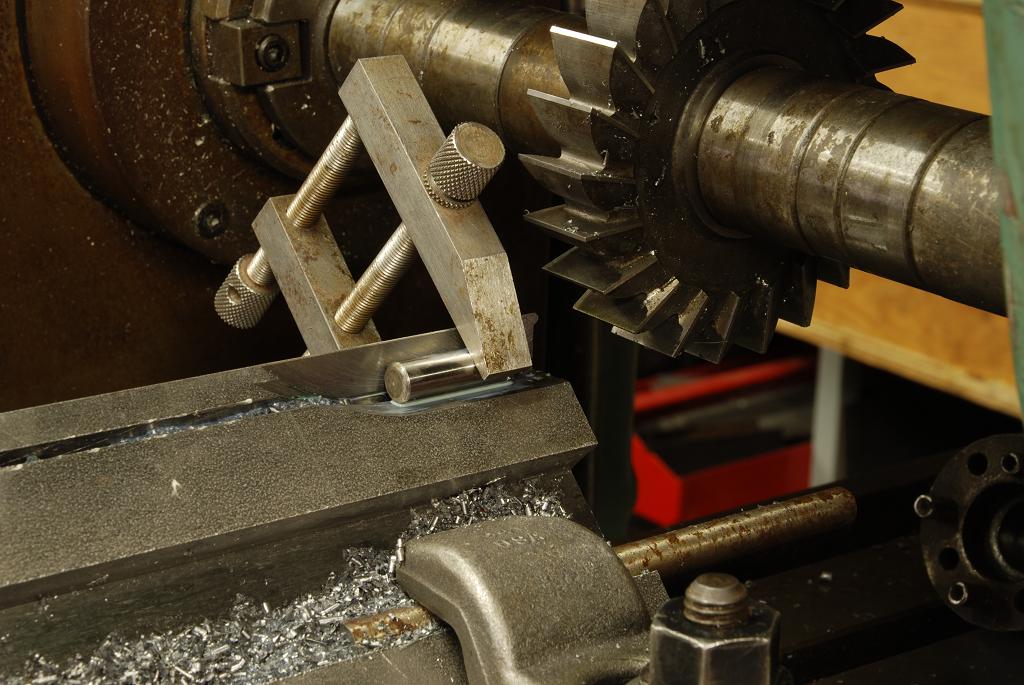
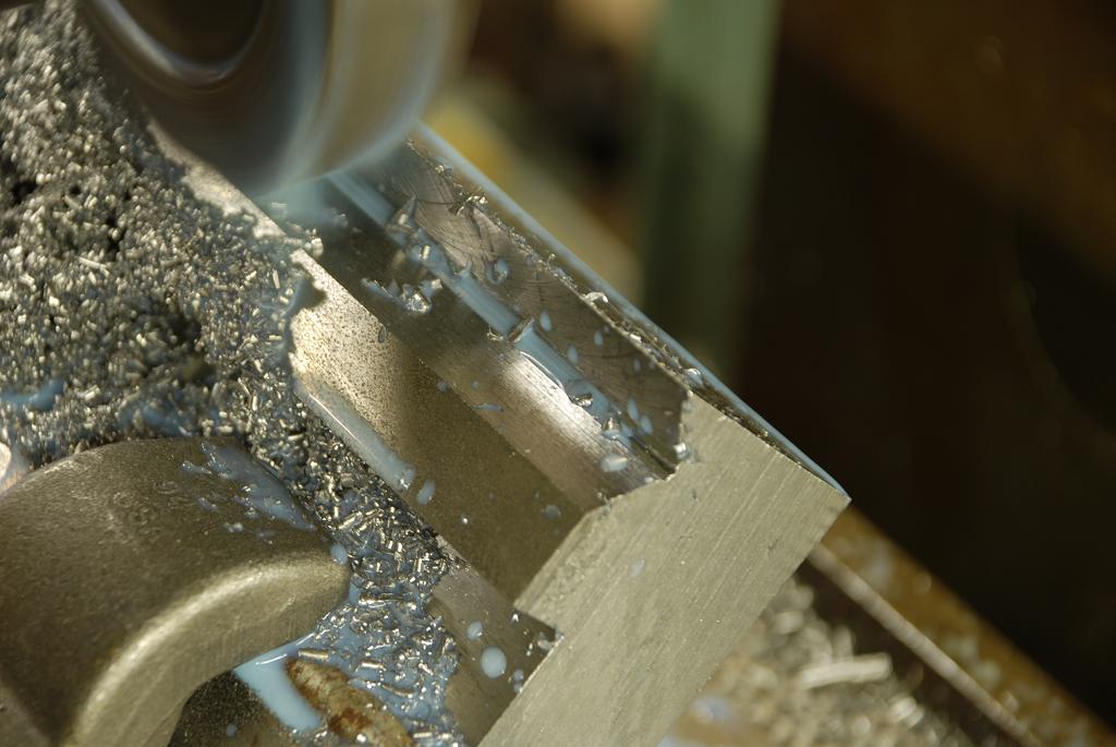
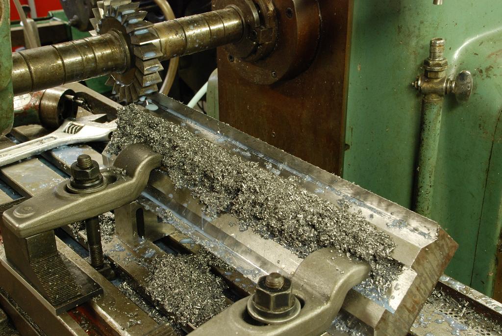
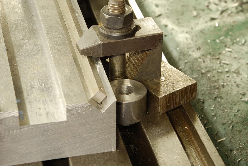
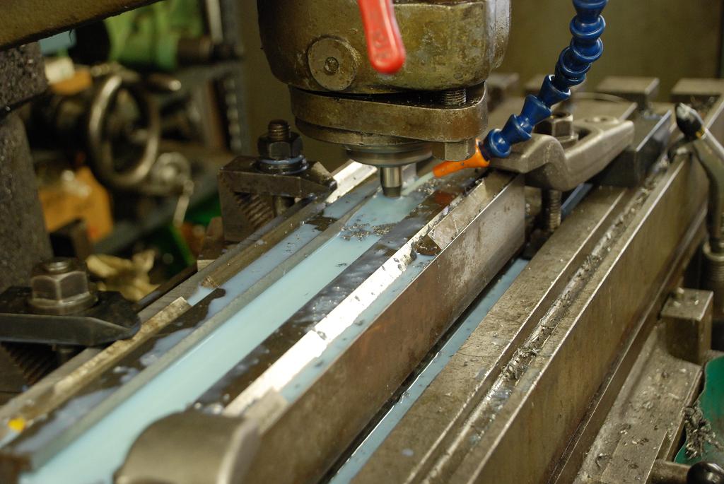
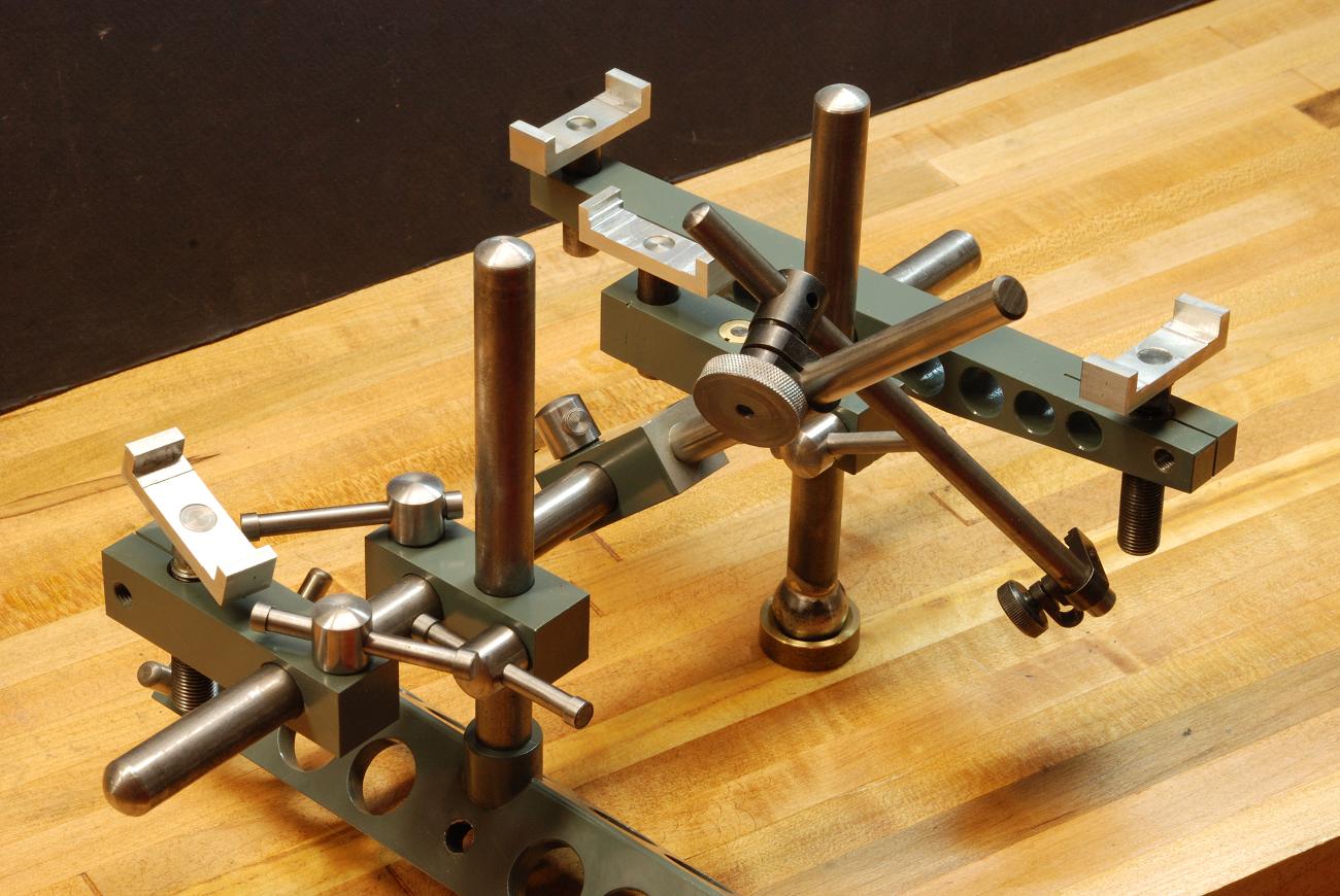
 
The Process
For a step by step account,  you get the back issues from Village Press.   It covers the topic in a lot of detail including how to make all the tools needed.
 
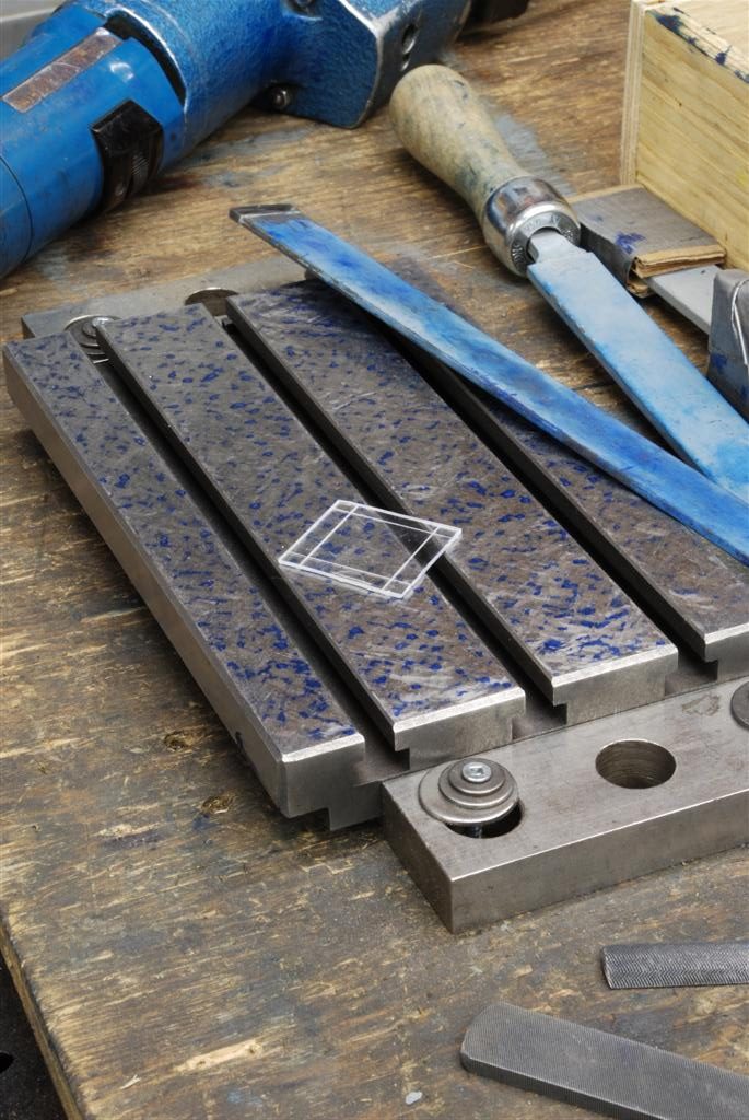
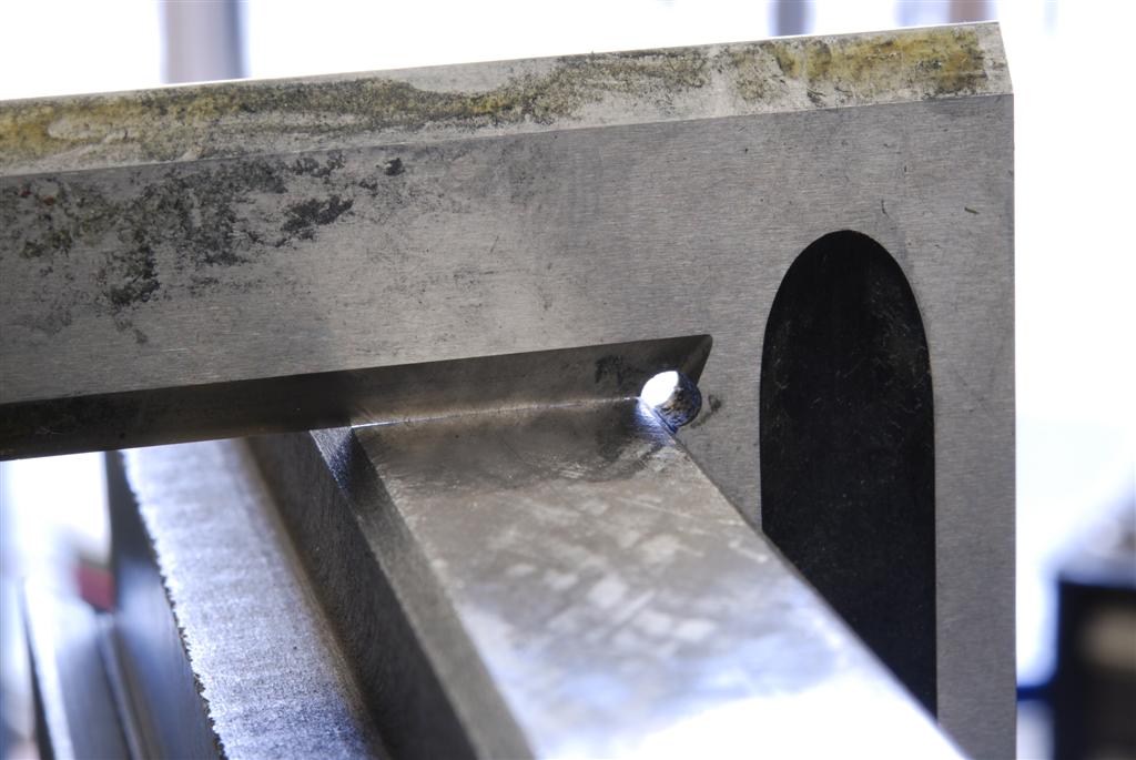
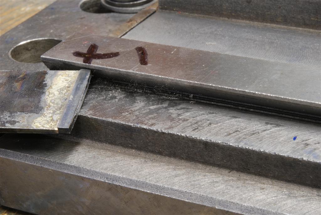
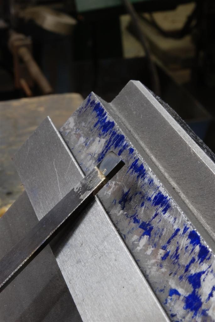
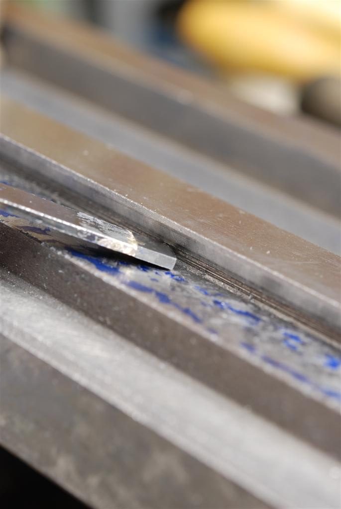
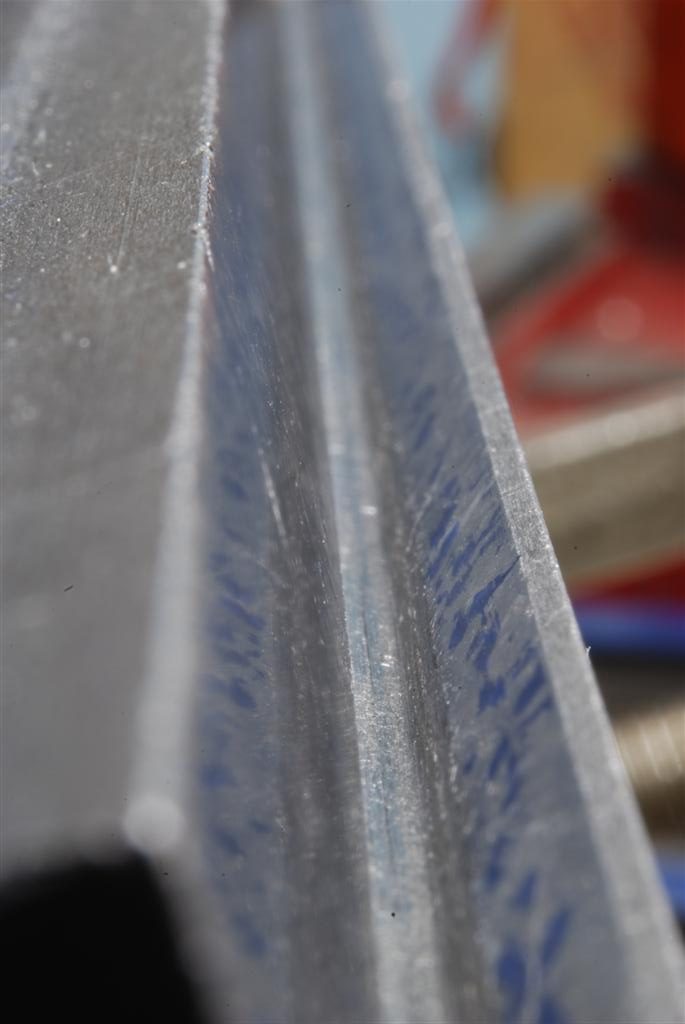
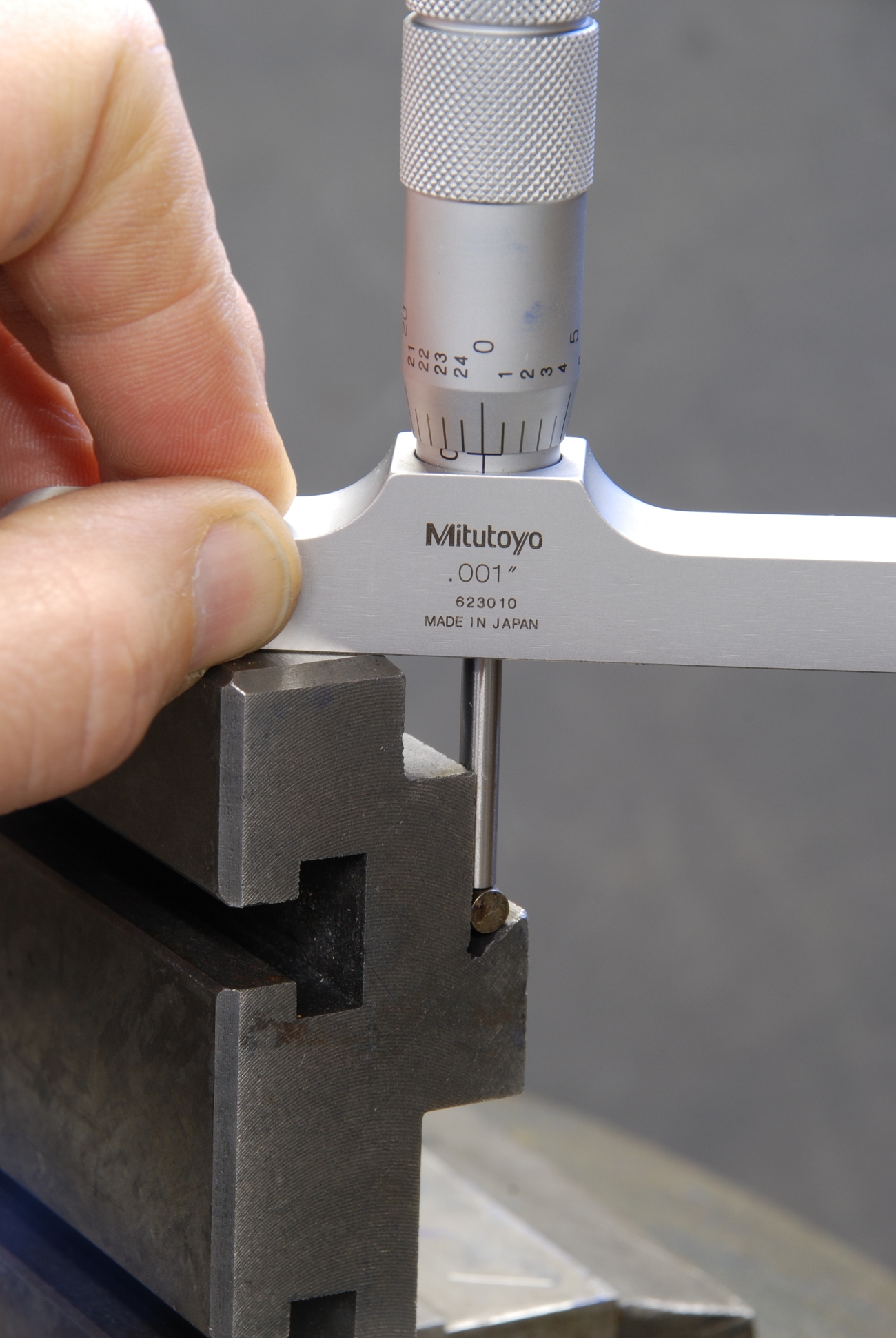
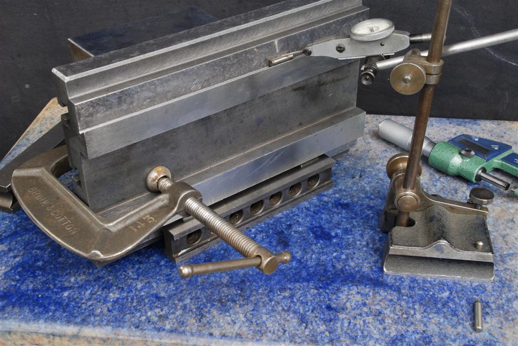
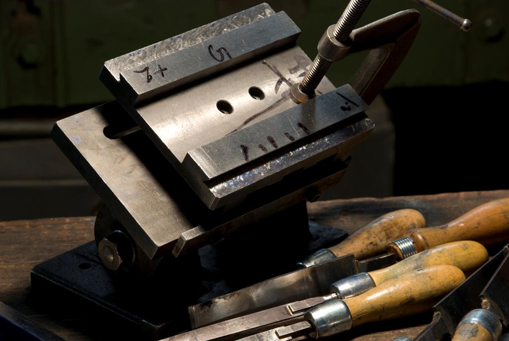
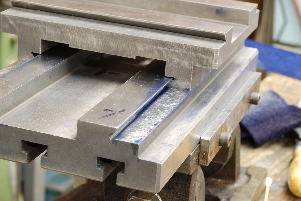
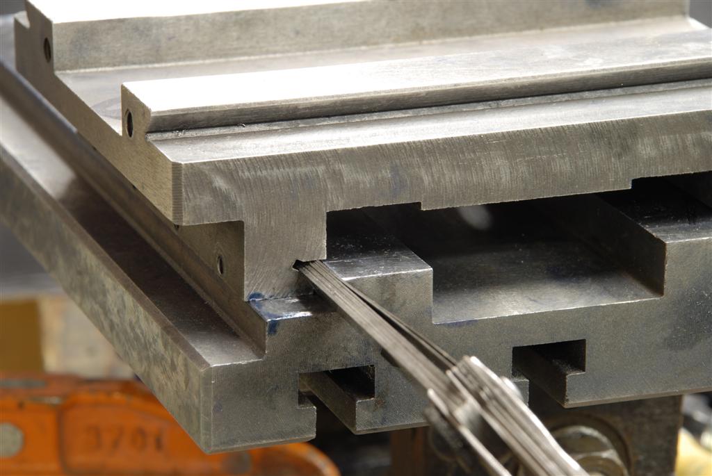
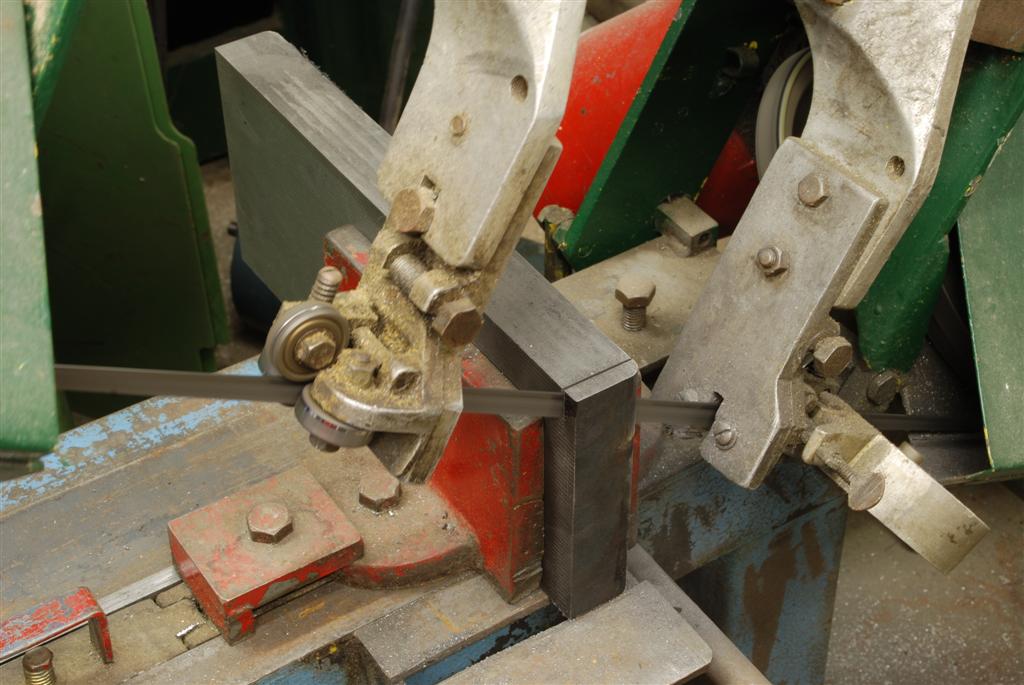
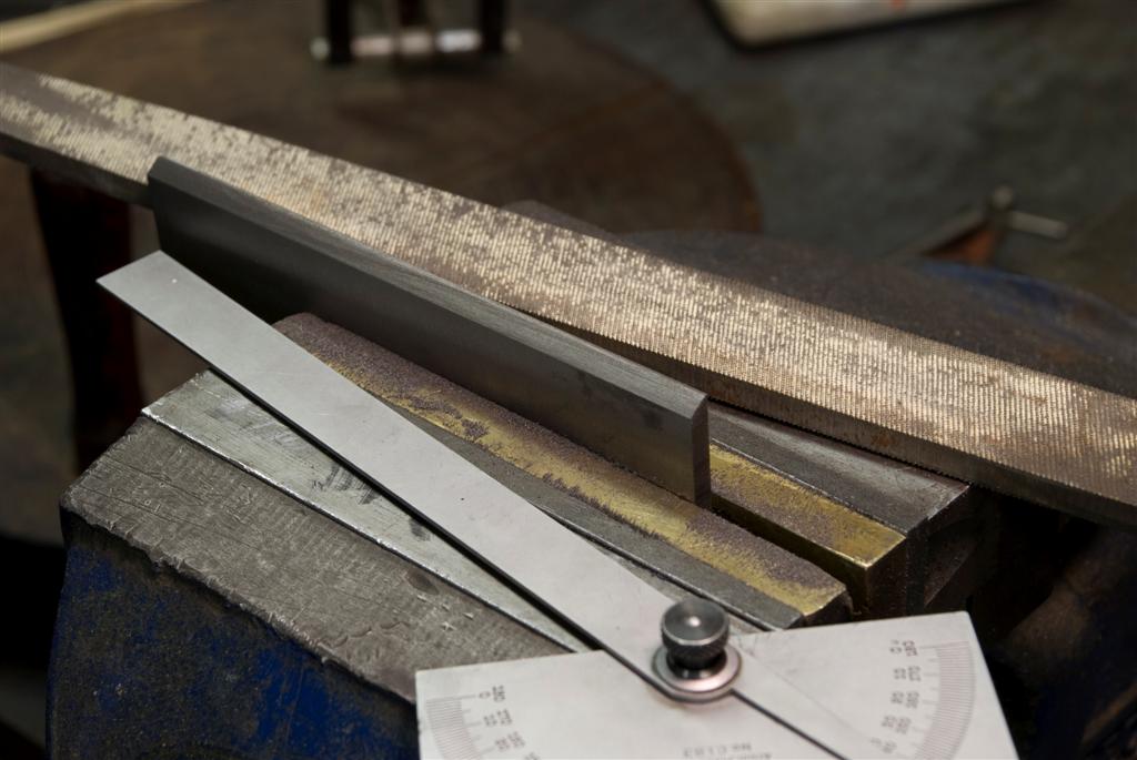
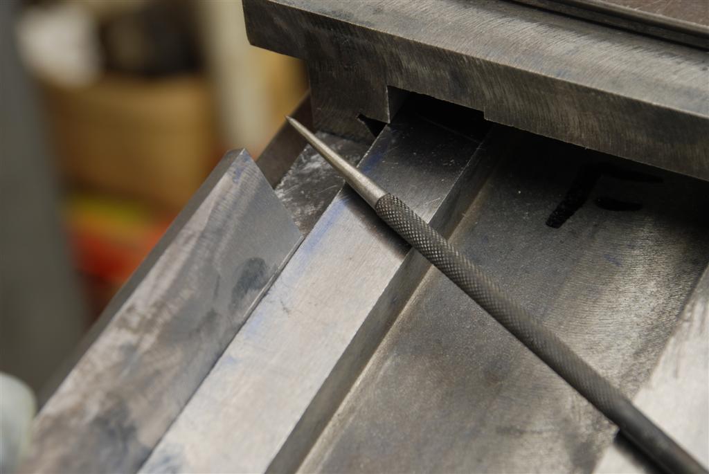
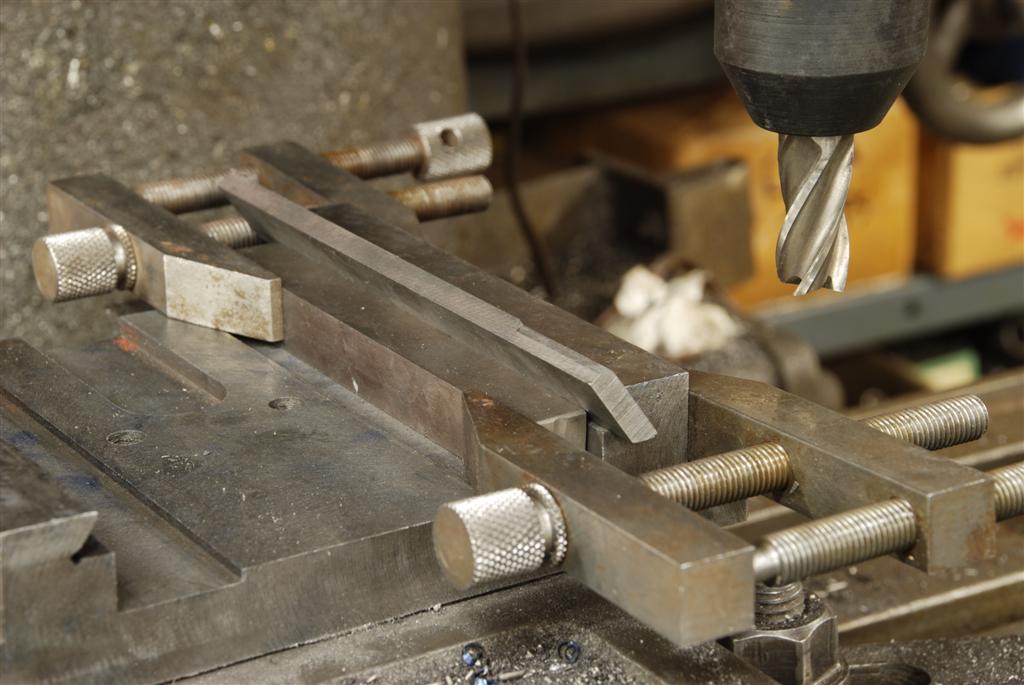
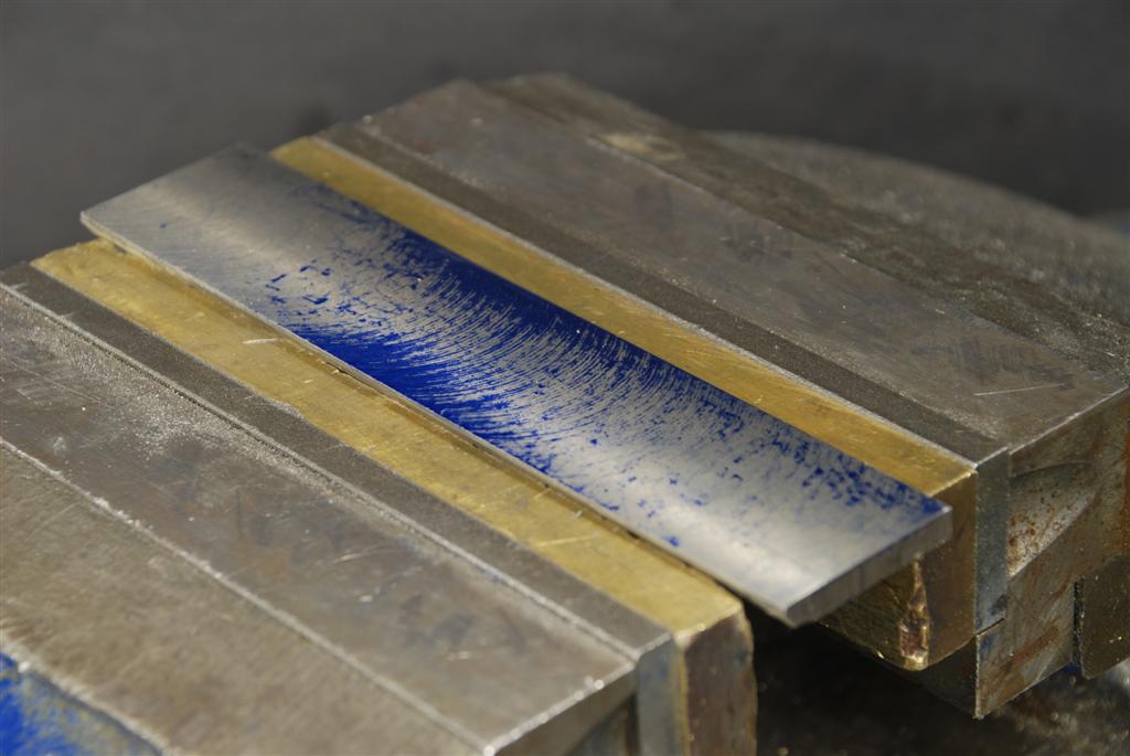
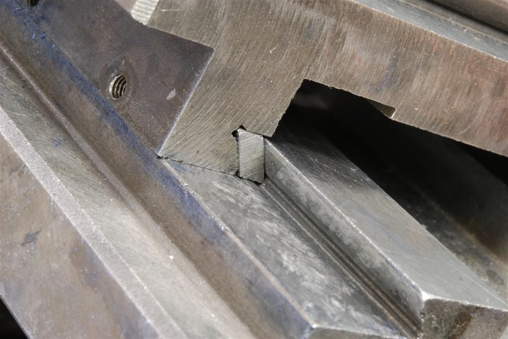
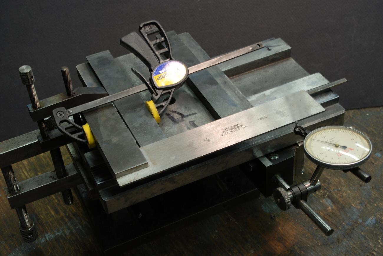
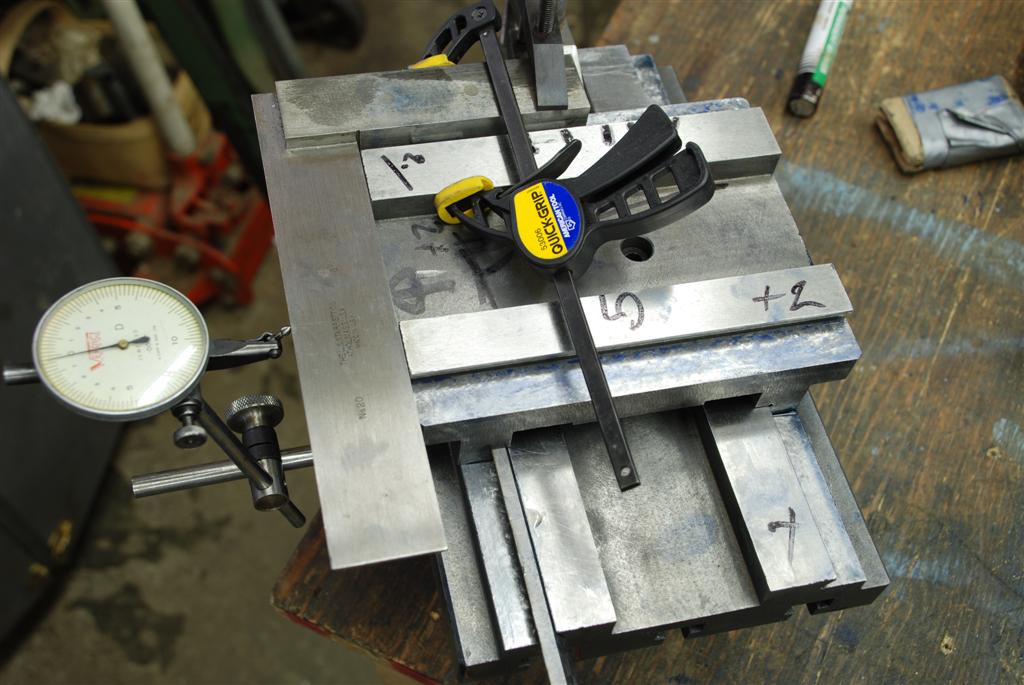
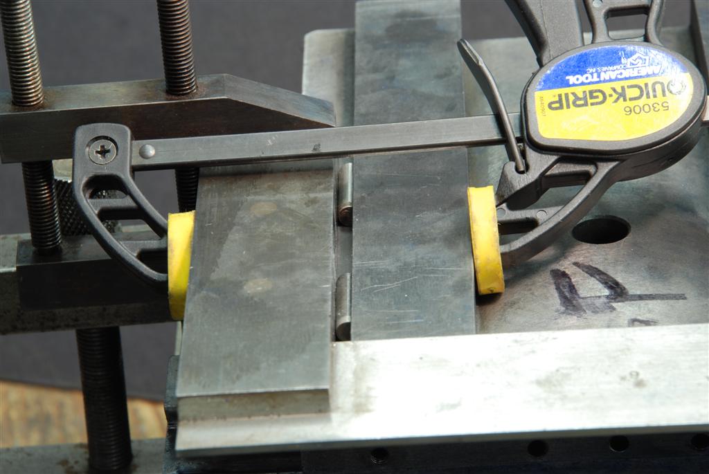
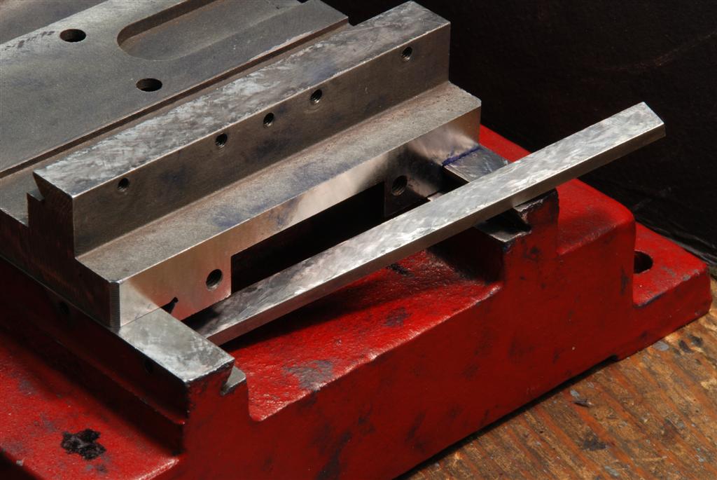
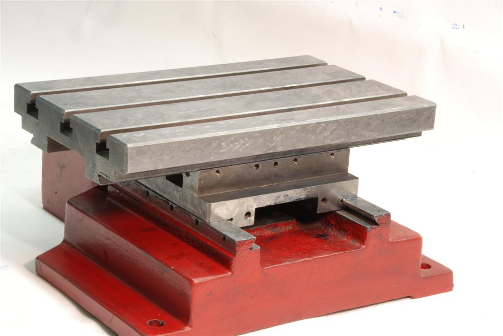
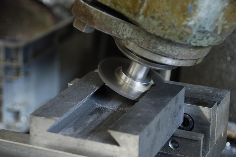
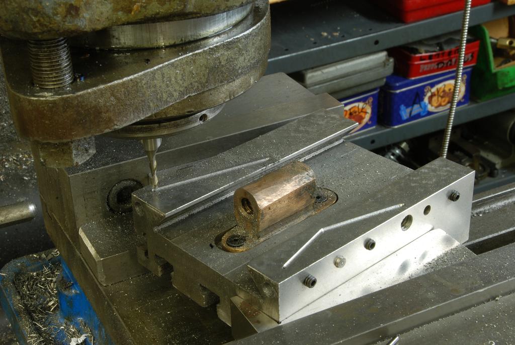
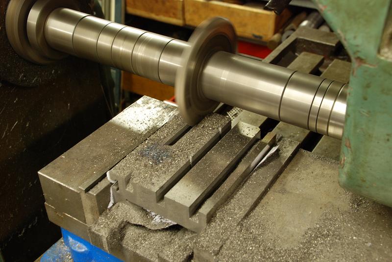
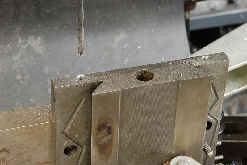
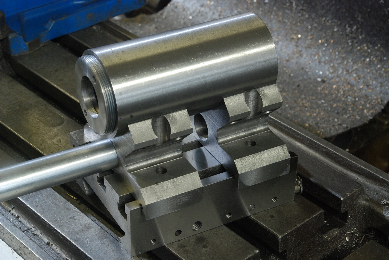
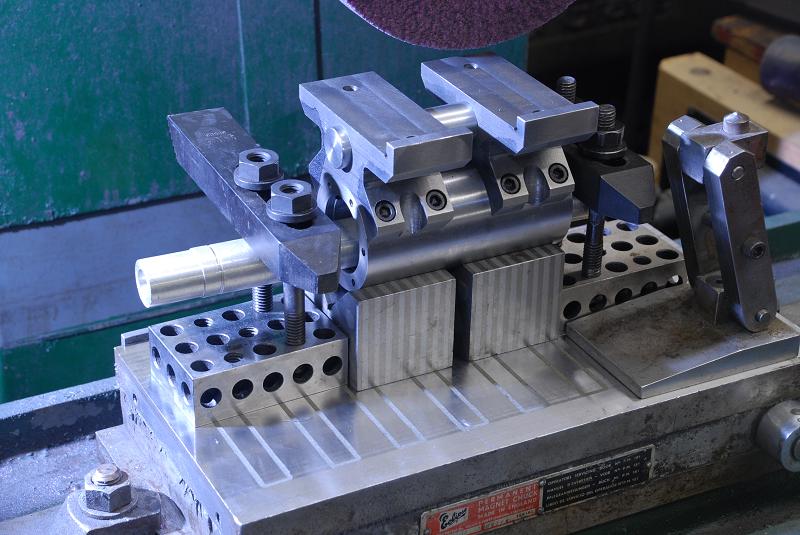
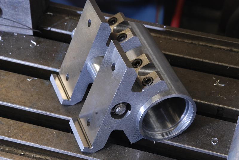
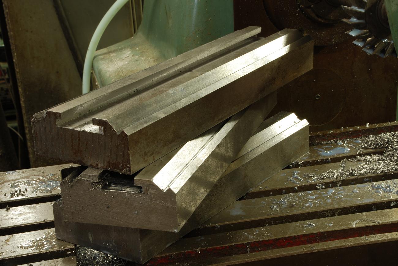
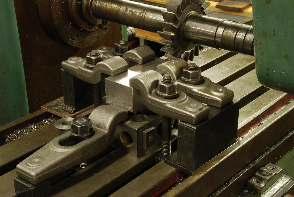
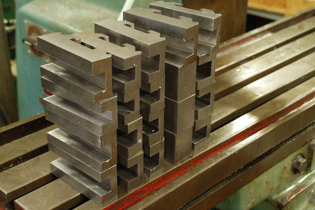
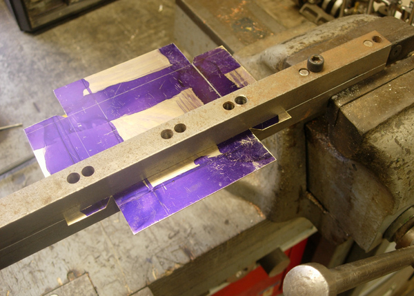
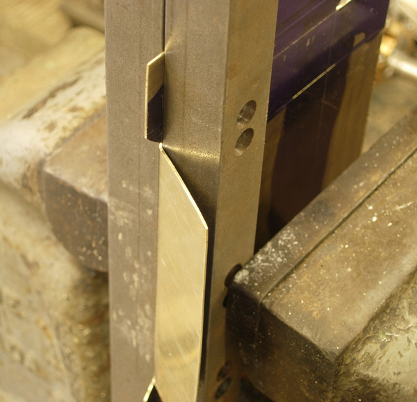
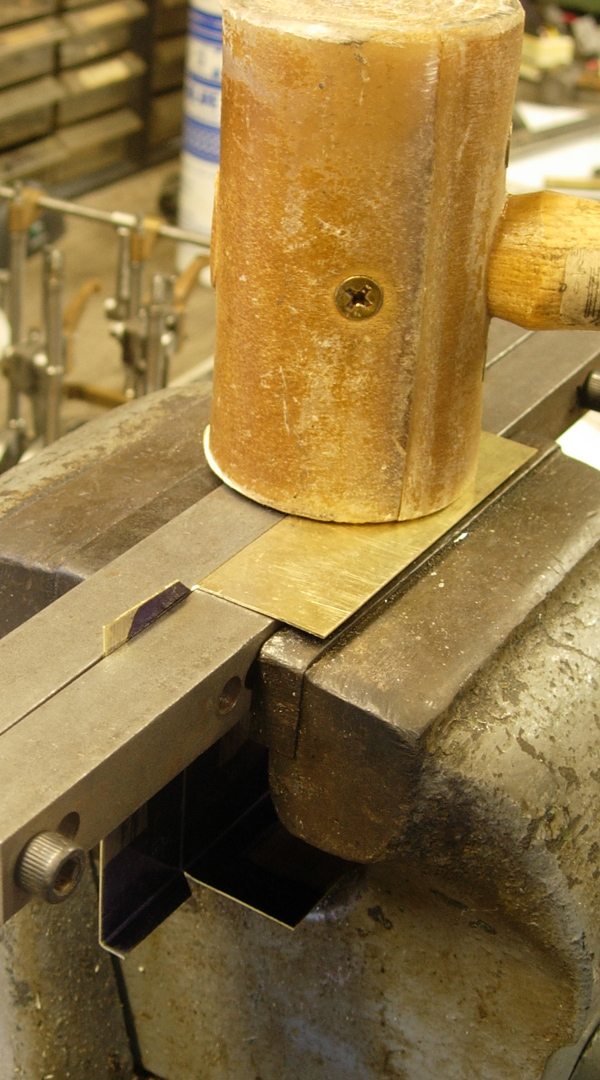
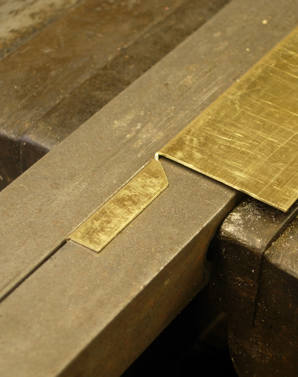
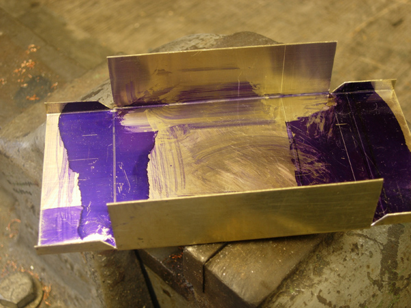
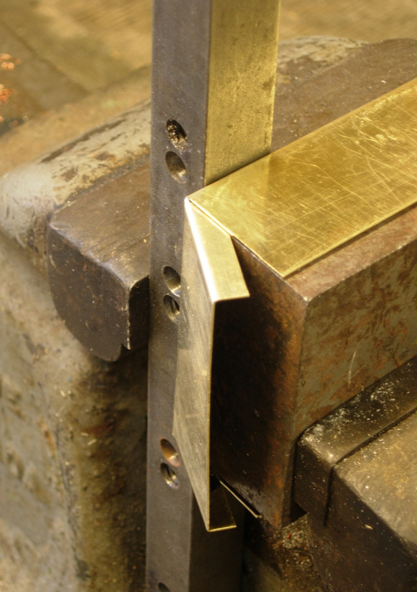
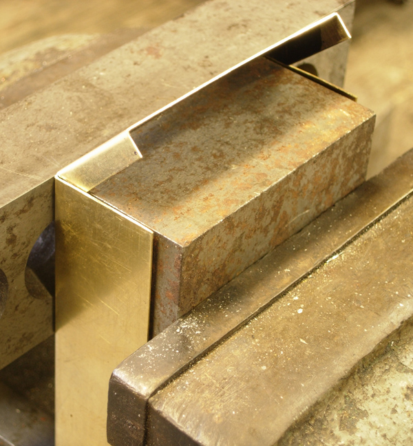
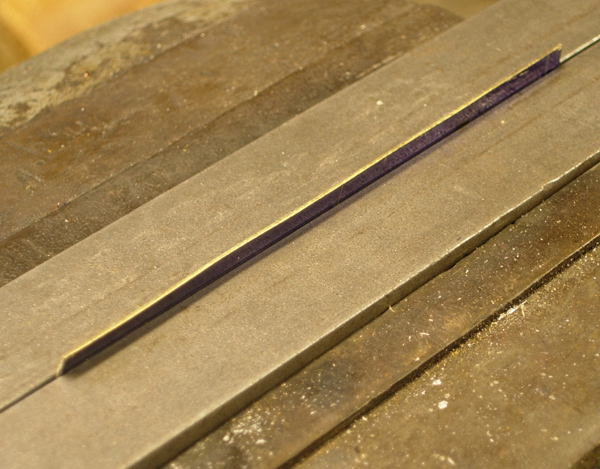
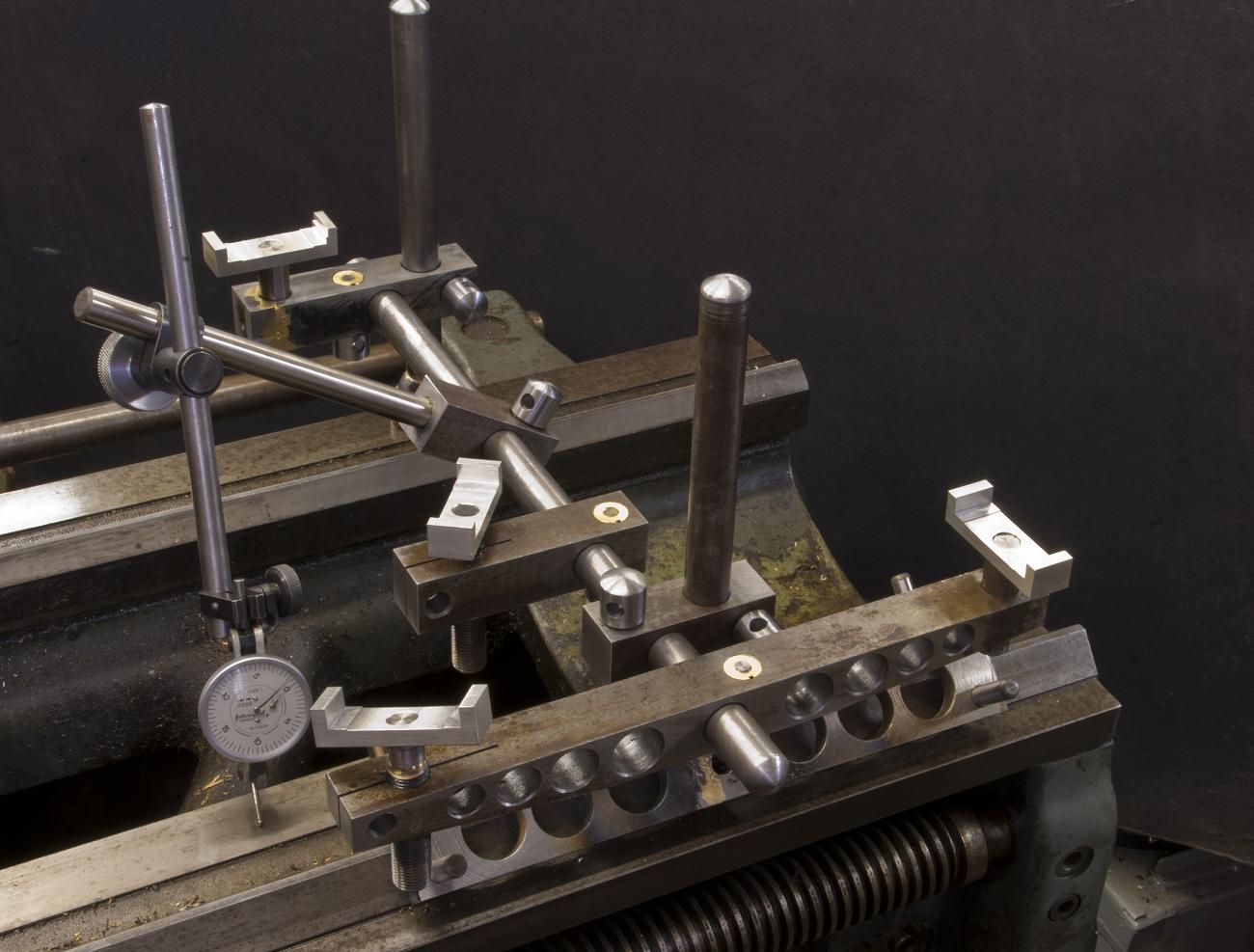
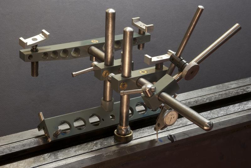
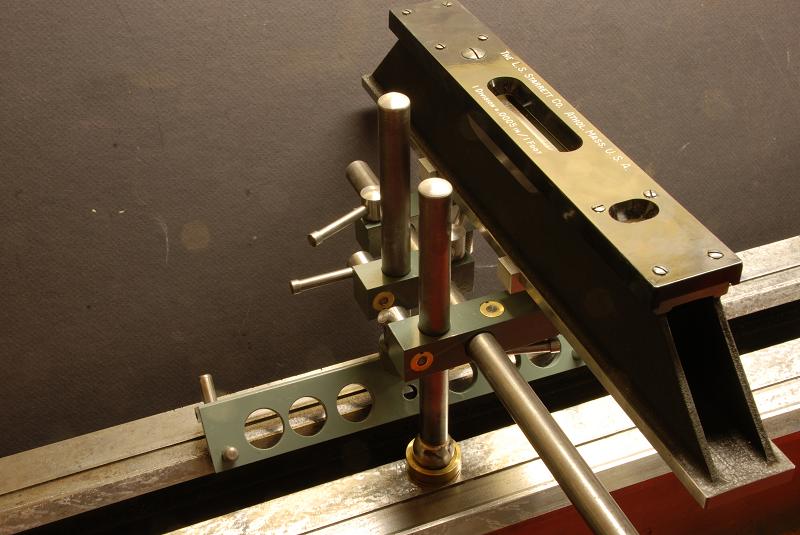
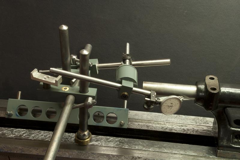
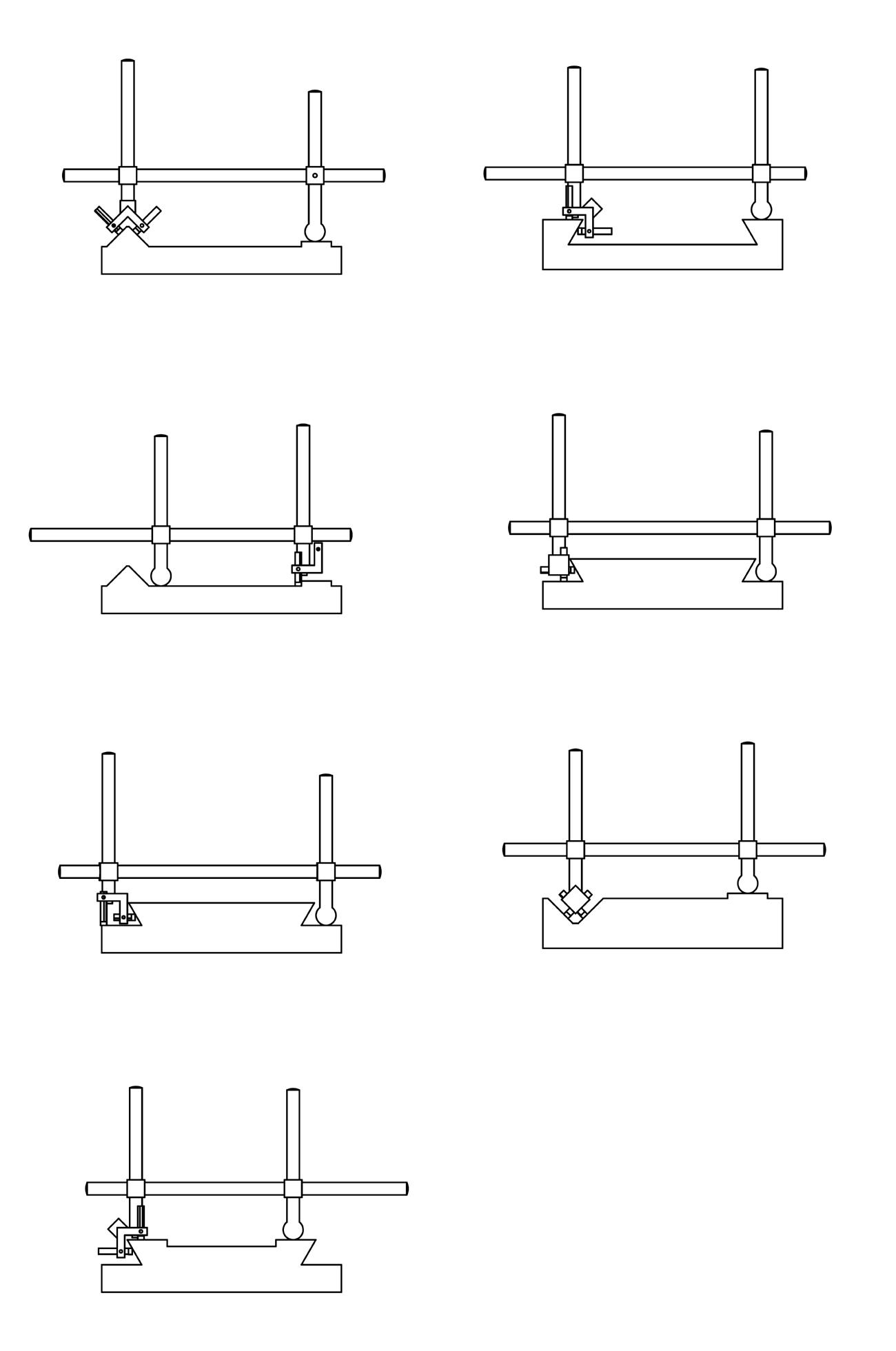
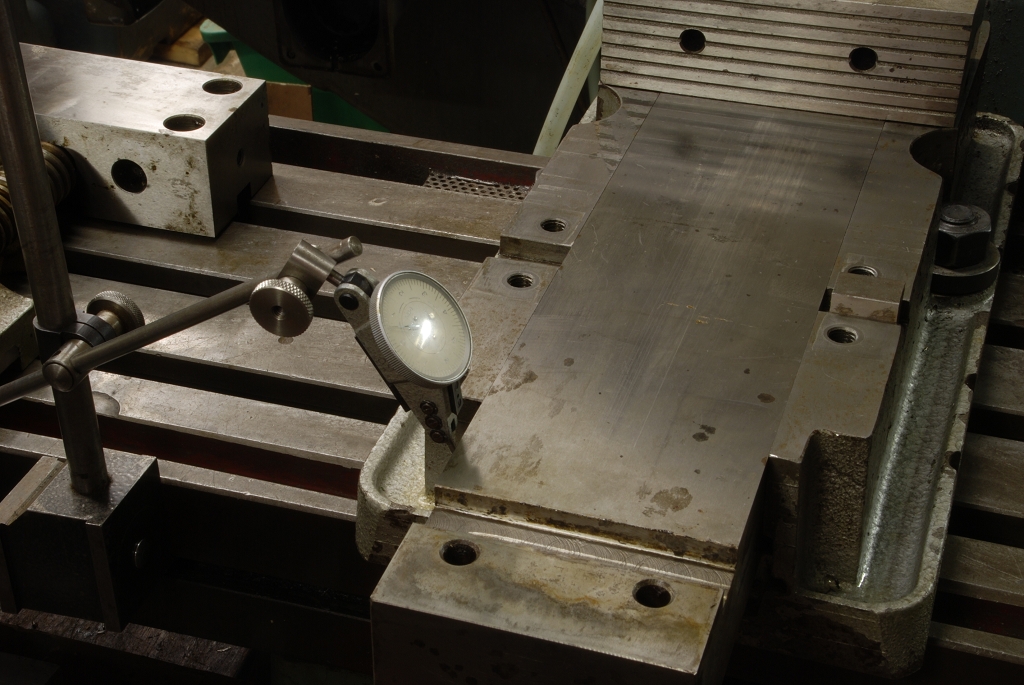
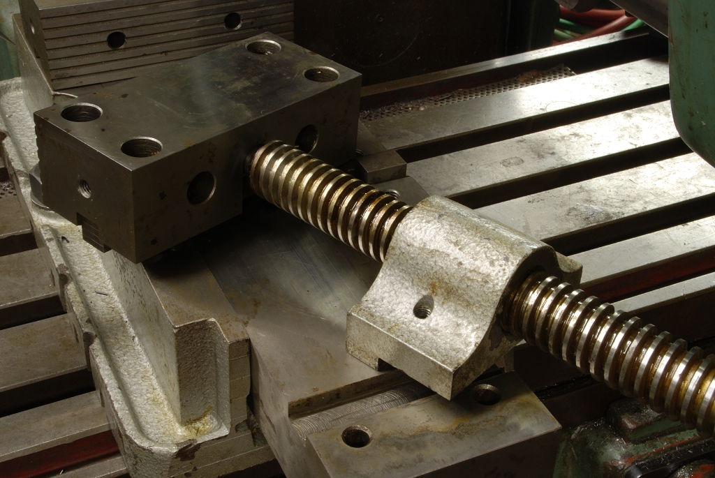
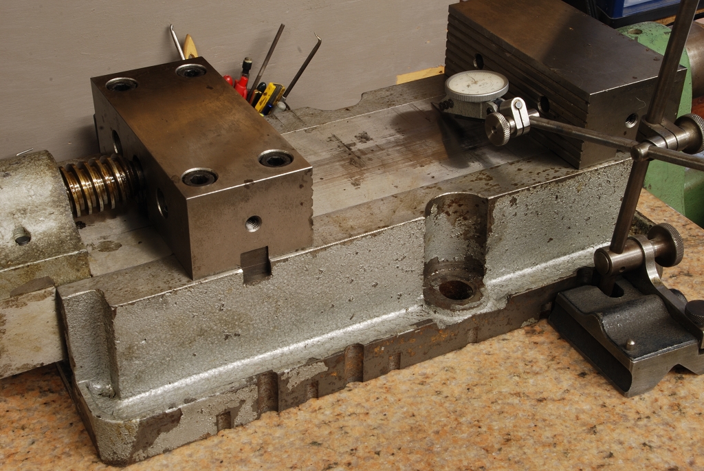
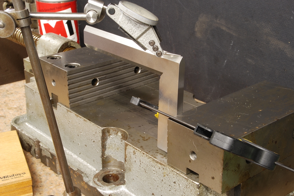
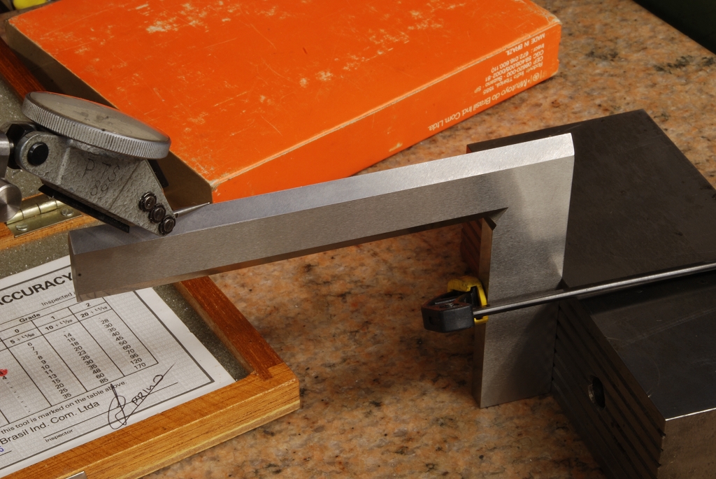
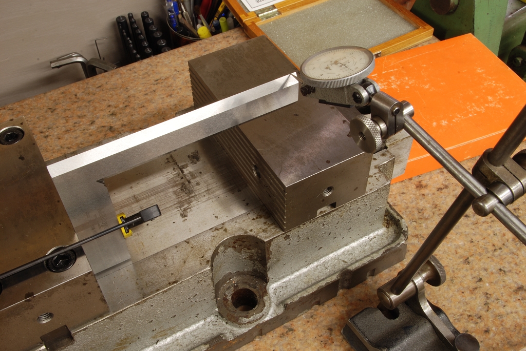
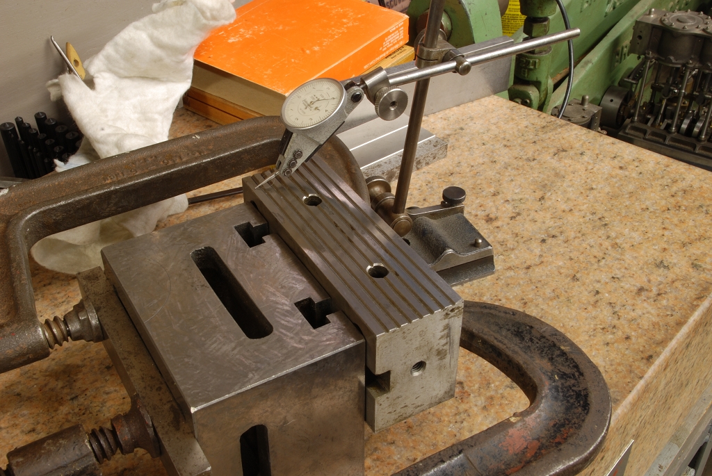
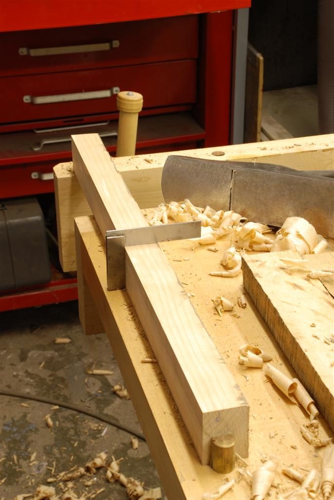
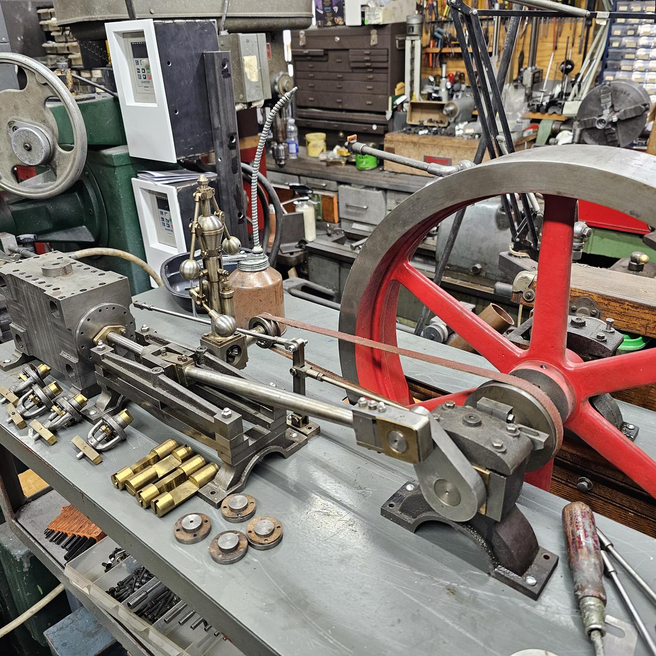
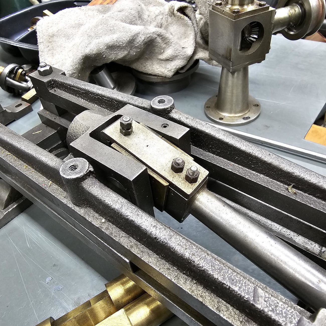
The photos fairly well sequence what I think is the “right” way to scrape a mill’s X/Y.  Some don’t bother with the front of the table, however its part of workman like approach.


Dividing heat spacer

Dividing Head Spacer


BCA Z axis

A new Z axis carriage and Spindle for a BCA jib borer


Making Dickson Tool holders

the only regret is not making twice as many

Brass Gas Tank

Thin gauge brass tank made with simple tools

GHT Pillar Tool

The clever and useful Geo Thomas Pillar tool.  I made this a long time ago.  I bought the casting set for the PT, but then they wanted almost as much again for the drill press head casting.

Feeling gouged takes away the fun so I whittled one instead

Deviation from the drawings, which I think improve it

I went with tommy bars and peened over the caps.  I find them more functional than ball handles – ball handles are stuck in one position whereas with a tommy bar you two

With the large tapping head, I fit the handle to the shaft via a filed hex.

For the small tapping head, I made a D shaped recess that gently presses on the shaft


Parts for a Schaublin 70 tailstock


I have a tailstock that came missing several pieces.  I also had a 3rd 70 I wanted to sell with the same tailstock, so before letting it go I made some duplicate parts.

The tailstock drawbar is a metric buttress thread – 45/5 degrees if I recall.  First time cutting an internal buttress thread but after some careful grinding f the tool it worked out well

The profile turning was done as one would on a wood lathe.  I held a large flat top piece of hss with a large radius in a vise grip and used a 1.25″ boring bar as a steady

Machine Tool Alignment Device

Machine Tool Alignment Device

My version of a Kingway.  If you scrape machine tools, life becomes so much easier with something like this.  It lets you detect the deviation of way surface by either an indicator or level.  Mine is for use with a Starrett 199 Master Precision Level.  The thought was most people scraping have one anyway, so incorporating it avoids having to buy the precision levels (we’re talking .0005″ per foot).

An innovation I added is a sweep too, essentially a precision spindle, that lets you indicate in a single plane geometry such as the tailstock quill.  In addition, there are several other improvements such as split cotters for powerful clamping and and an invert V shape with movable feet allowing its use with a wide variety of ways sizes and geometries.  The feet have brass pads so the unit doesn’t scratch the ways as its used.

A full build article and instructions for use have been published in Home Shop Machinist.

Mill Vise - Review, Surveying and Correction

Mill Vise – Review, Surveying and Correction

I acquired this new vise iwith a fixed forward jaw arrangements. I bought a
new Kurt last year and have liked it a lot, was looking for a second
(tired of moving from between machines) when i came across a kijiji guy
selling these. He snickered when i asked how it compares to the
Kurt….some salesmanship for sure, but he believed it. He says he
used to have 70 of them in cnc production shop he wound down. His
business now is a odd mix of a job shop and importer from china/taiwan
of everything from vises like this to camera stuff. One thing he showed
me was a 3′ handle – said they they used some as presses and they
never complained

As it wasn’t immediately apparent to me the action of this vise I took a
few pics for the curious. Apparently its a knock off (Taiwan) of some
European vise that sells in the thousands. Just saying what i was told.

What I like about it is deeper jaw than the Kurt, has the same
anti-lift feature, through holes in jaws for attaching sold jaws, much
more smooth to clamp and undo and the biggest one is the entire area
under the work can support things (whereas the centre of the Kurt is a
no go zone)

I bought it for $250 used, new they’re 450 (time marches on…that was 2012). Initially attracted by price, I’m impressed with it.  Its general shape of the Gerardi, but different operation. I’s badged aKR machine vise and distributed by D&R in Oakville….just not sure what they are copying…vendor said its a copy of a Gerardi but clearly its not if you look at the operation of the two.

On checking accuracy, it looks like I won’t be using the Kurt as a doorstop quite yet. This thing is a fail, although fixable.

The first test (5th photo), indicating the bed of the vise showed incredible
accuracy. No more than a 1/10 in both directions…impressed after this
test

Then I put a square on the moving jaw and indicated it this jaw is fixed
to the moving bar so should be dead on . Unbelievably, its out 005″!
How can this be – you make a vise with one part to 10ths and then the next like this? Grrrrr.


In next photo, the moving jaw is a the back and part of of this large bar that drops into the channel in the base. There 1/2 a thou play on the indicator


I figure the only fix was to grind it square. My set up using a block i
know is good. Indicated one more time just make sure i wasn’t missing
something.

off to the grinder – gratuitous action shoot. Does show well though how
with short overlapping passes one side of the wheel does all the work
leaving the other unworn to spark out. Its a fairly light cut, looks
like a lot more but that’s just the slow shutter speed capturing a lot of
sparks


Finished! Bit of POS imo to be that far out so beward ….but with the grinder was able to go for the save!


Sprucing up an Altas shaper

This shaper spent most of its life dissembled in a local characters basement.   The biggest challenge was finding parts – we never did find the base casting.  How do you lose a base casting?

Anyway, I scrounged around ebay and made some parts and bought others.  There was literally no wear on machine, like it had never been use so my work mostly aesthetic on this one…vs the my oft employed “make it mechanically perfect and who cares about the paint, because after a year of chips and coolant it’ll look like crap anyway” approach.

I turned out well, but alas, space constraints meant it had to go. 

Madman Mike's Toe Jack

Warning – Lifting and moving machinery is risky business.  Making lifting devices is even mores so.   This is for experimentation.  If you build something similar its at your risk

Credit where credit is due….I copied this from Madman Mike.  If you have to move machinery, buy or make a toe jack….it makes it so much easier to get the machine up onto or off of rollers, blocks etc

I’m embarrassed by those welds, but it works (better not let the guys at work see them)

A neat trick Mike showed me is to unscrew the jack all the way (it won’t come out all the way).  Hacksaw it off with say 1/2″ protruding.  Then hacksaw a slot in the protruding bit and screw it in, all the way to the bottom (just gets it out of the way)

Now, you can use the acme thread section you cut off as bolt to hold the whole thing together

XLO Spindle Bearing Replacment

It was time to replace the bearings on my XLO mill. 

Popular belief is that if you undo the bottom beaing retaining nut, the spindle will just drop out.

Not so!

Well, it is so if your mill is one of the spindle design shown the manual scattered around the net for download, however there there is a second that has an upper shoulder on the quill (spindle housing).  The spindle shaft cannot come out with removing shaft retain nut at the top.

Easiest way to remover the entire spindle, housing, bearings and shaft.

Then with with spindle on the bench make a nut undo the upper nut.  Tap the spindle out gently.


At the same time I did the upper throw out bearing.  To remove the yoke (you have to press in the new bearing) the motor needs to be lifted up and the top have of the pulley removed

Models

Fire Eater

Not really a model (there’s no prototype) but a fun little engine none the less.

This engine was designed by Phil Duclos and appeared in Live Steam magazine many years ago

My contribution to the design was cementing a rare earth magnet in the fuel tank and a bit of steel in the aluminum base.  I found good running depends on exact placement of the flame and this makes it easily adjustable

Perkins Hit and Miss


Stuart 7A

Rider Ericsson Hot Air Engine

Stuart Triple Expansion Marine

Brass V4

Corliss Engine (the Giant)

This amazing and large engine is the work of 

It came to me unfinished without drawings so I’m working in the dark.  I purchase some Cole’s Corliss drawings eons ago that should be give enough info adapt the various bits to this engine.

If you have one of these or can shed any light on it, I’d love to hear from you