A diminutive project of king sized proportions. It must have been run dry because the condition of the spindle bearing and the shaft was like that of a farm wagon hitchpin.
Its a plane bearing lathe so no convenient trip the bearing supplier. Whats worse, the bearings the typical watchmaker/instrument lathe biconical format – two tapers, end on end that must mate perfectly and lapped to the finest finish. It its about an impossible machining task with specialty built fixtures and machines
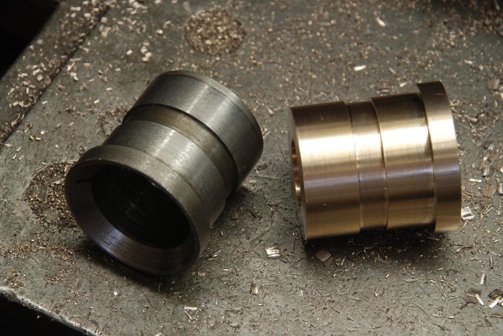
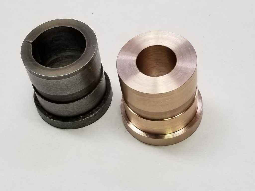
Hear is a shot of the original hardened steel bearing. A worn out, scored up mess. The spindle shaft was also in poor condition but salvageable. Lets start there
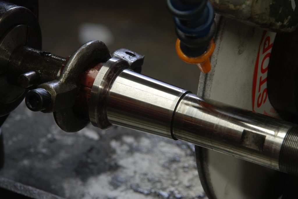
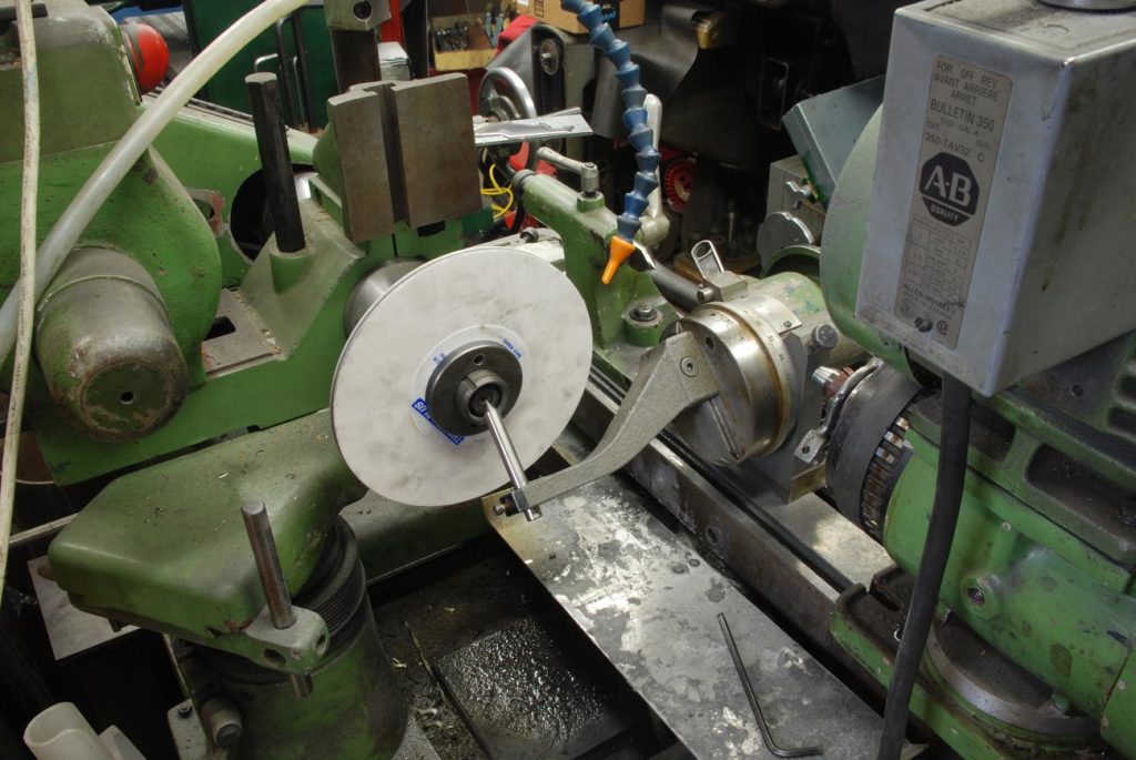
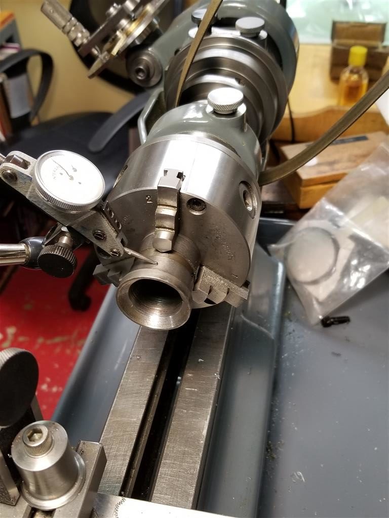
I’ll start with grinding in situ a taper that will fit the internal taper of the spindle. This is give us a fighting chance and concentricity
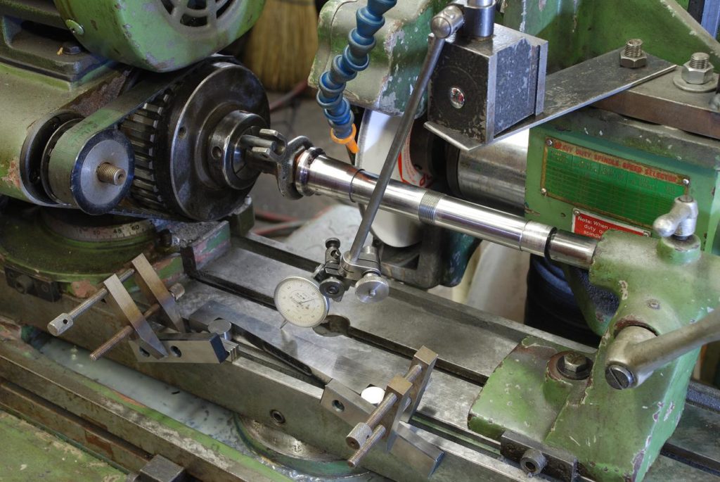
runout is checked and is less than tenth. I only have one shot at this so I spent a lot of time checking and rechecking before removing any material
checking for alignment. I need to just kiss it enough to create accurate surface. If I remove too much, I won’t be able to take it up with bearing adjustment and will have to get the part hard chromed and essentially start over
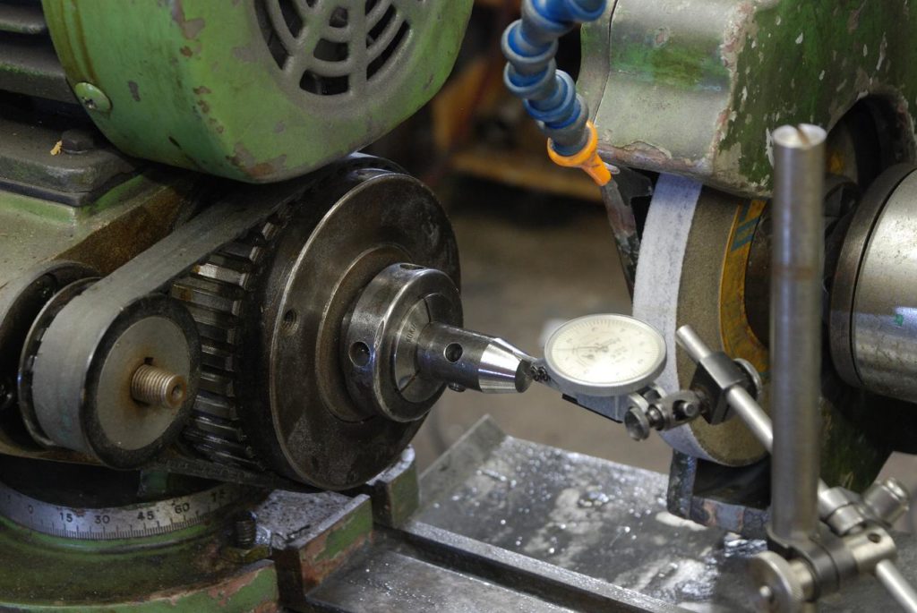
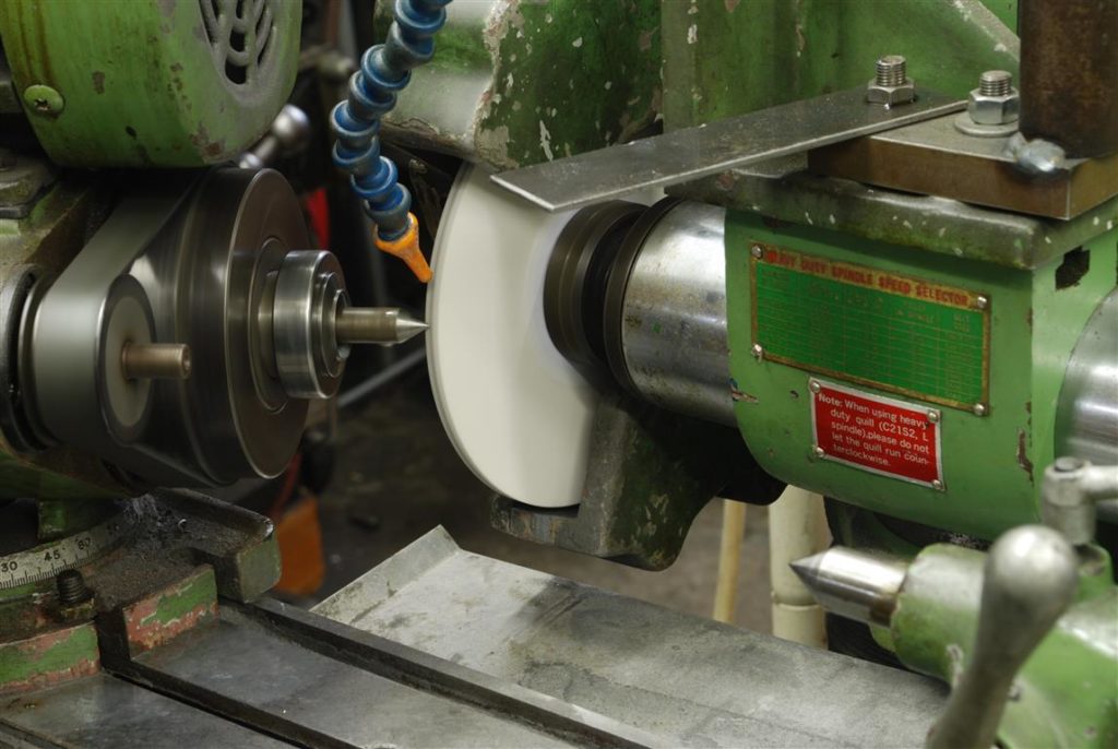
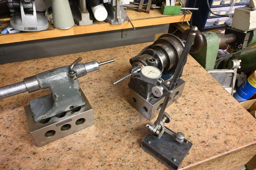
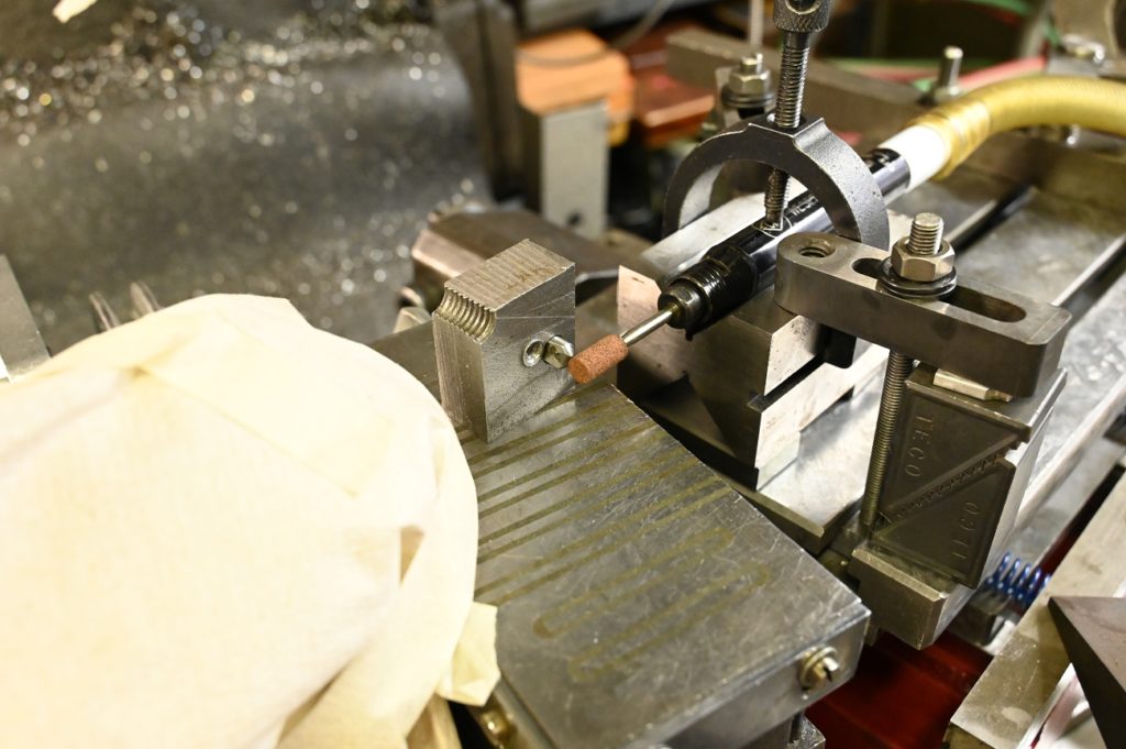
When every you are machining a taper, turning or grinding, the cutting edge as to and the centre height of the work. A convenient way to achieve is the compare the level between the grinding spindle and tailstock centre. I machined a small block of steel the right dimension so I could raise and lower the wheel to get it exactly on the centre height of the work
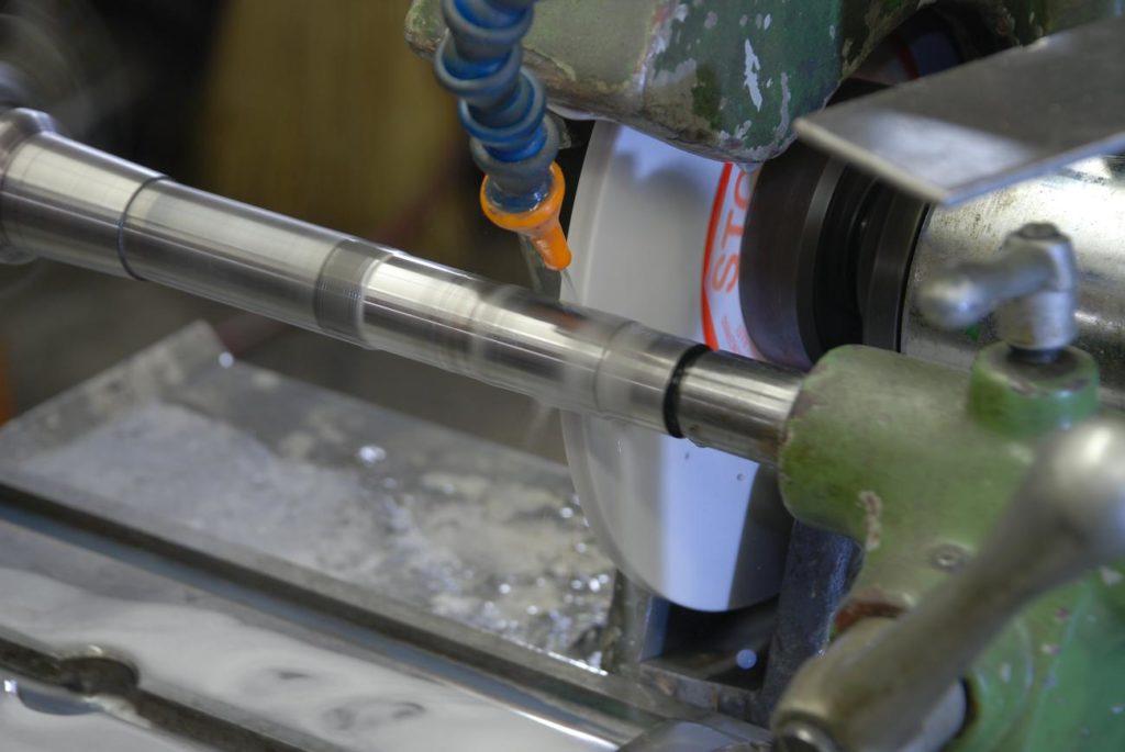
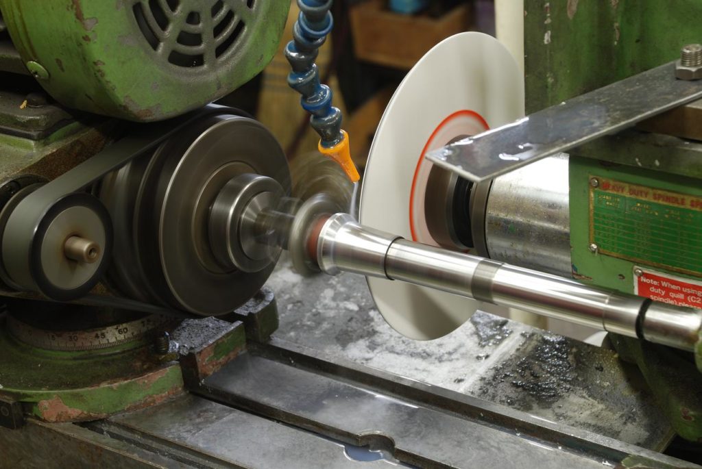
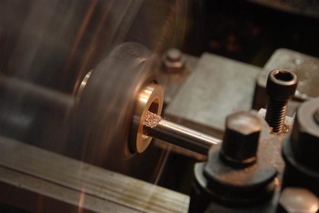
grinding the straight bearing section of the shaft
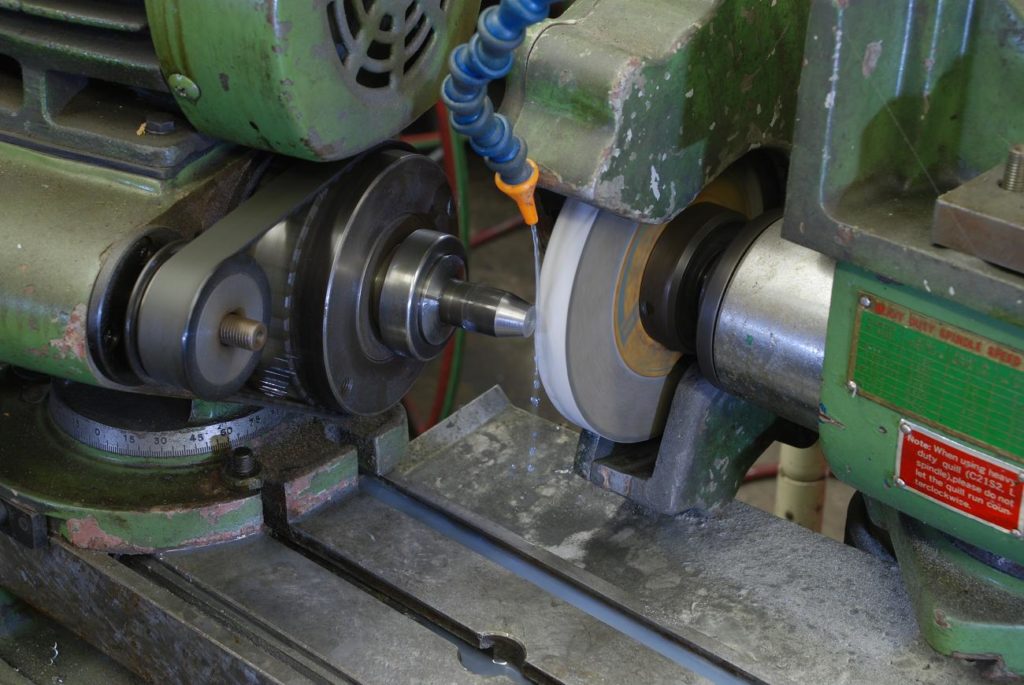
I’m using a very fine (150) wheel which is also fairly narrow. My grinder is a tool grinder with a motorized workhead so is light compared to a proper cylindrical grinder. I find these narrow find wheels work well with it
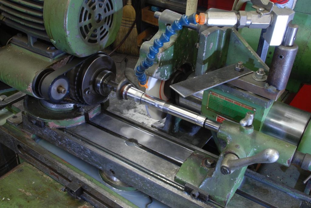
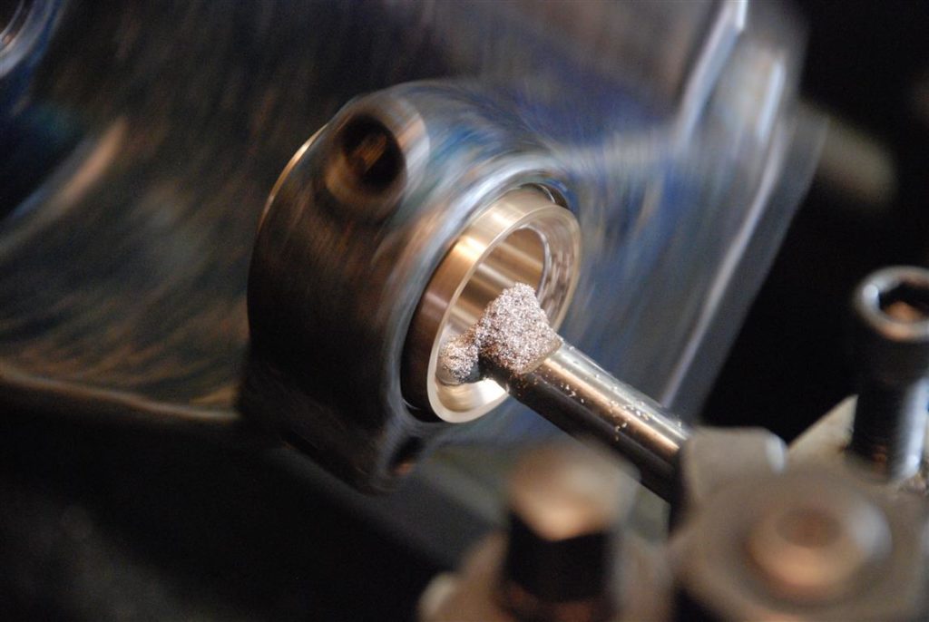
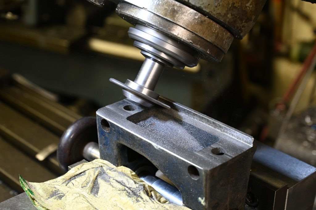
More complicated is the 3 degree tapered bearing section. Here the table top is being set to 3 degrees
and grinding commences! Because of clearance with the T slot etc, there is no guarantee I’ll get exactly a 3 degree taper,. however it will be very close the final fit will be via scraping
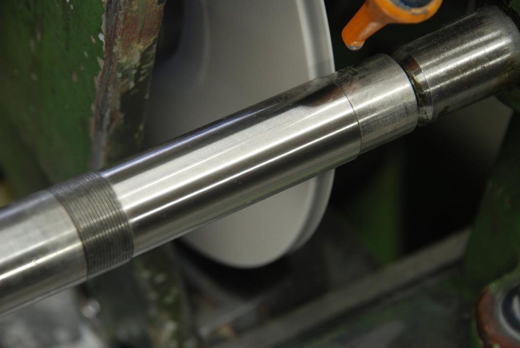
I’m happy with that finish.
The final section to be groundis the 45 degree taper which presents some challenges. Correct grinding procedure is to have the wheel traverse back and forth so an averaging is done. You don’t plunge with a cylindrical grinder and hope for good results
However I had little choice in that the most important thing is its all ground at this set up – that creates perfect concentricity
The plan is to dress the wheel at 45 degrees, every so gently plunge, then using hard Arkansas stones polish the surface to remove any rings
Its key to dressing the whell properly that the dressing tool move through a plane intersecting the spindle axis
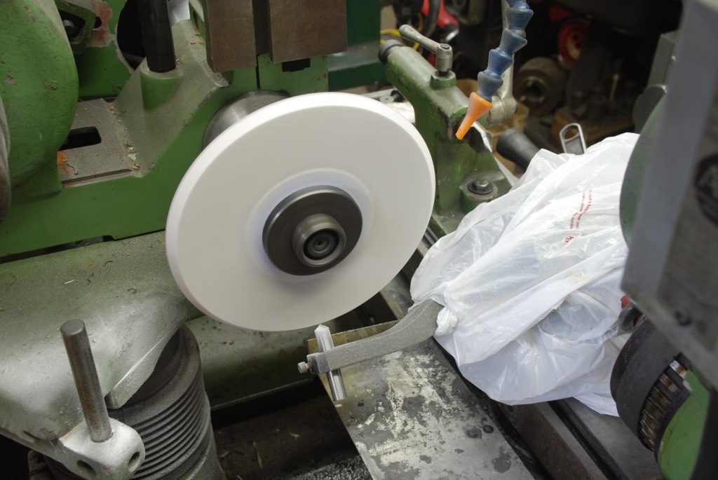
Here I am dressing the wheel. Note how the radius dresser is covered with a plastic shopping bag. It’s a precision bit of kit we don’t want covered grit.
And the cut is made
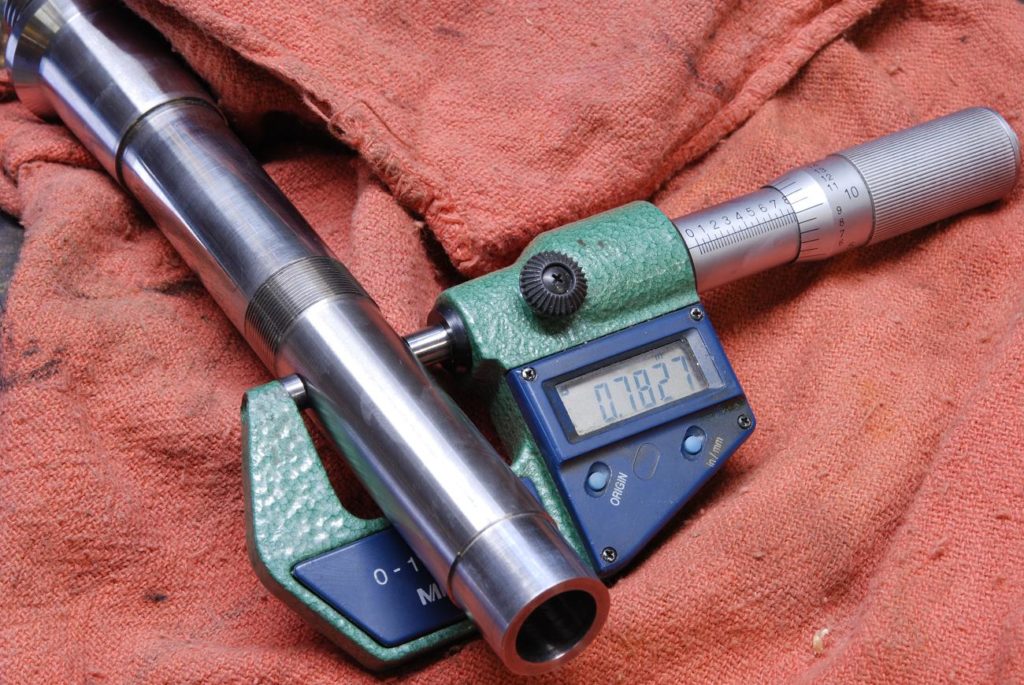
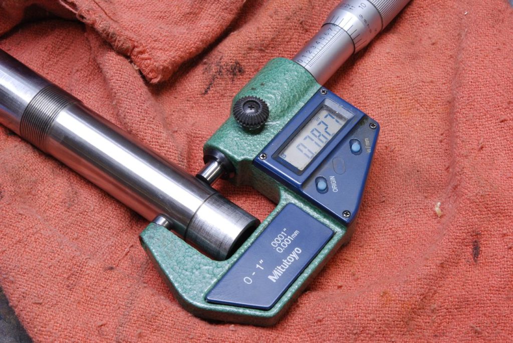
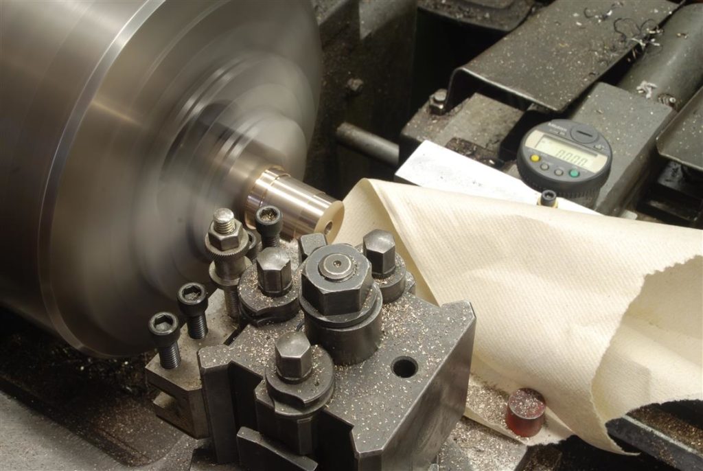
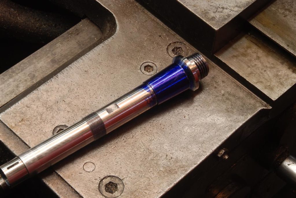
Inspecting the shaft, with a tenths mic, I’m getting the same reading End to end
The final operation for the shaft is too mounted in the lathe and with a hard Arkansas stone polished surfaces. These stones are so hard you’d have to sit there for a long time to appreciably change the geometry of the surface, however they will take off the microbe burrs etc. leftover from grinding.
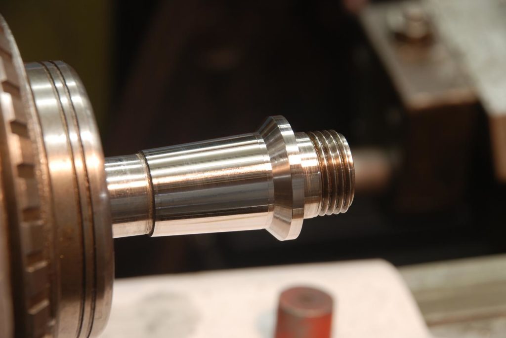
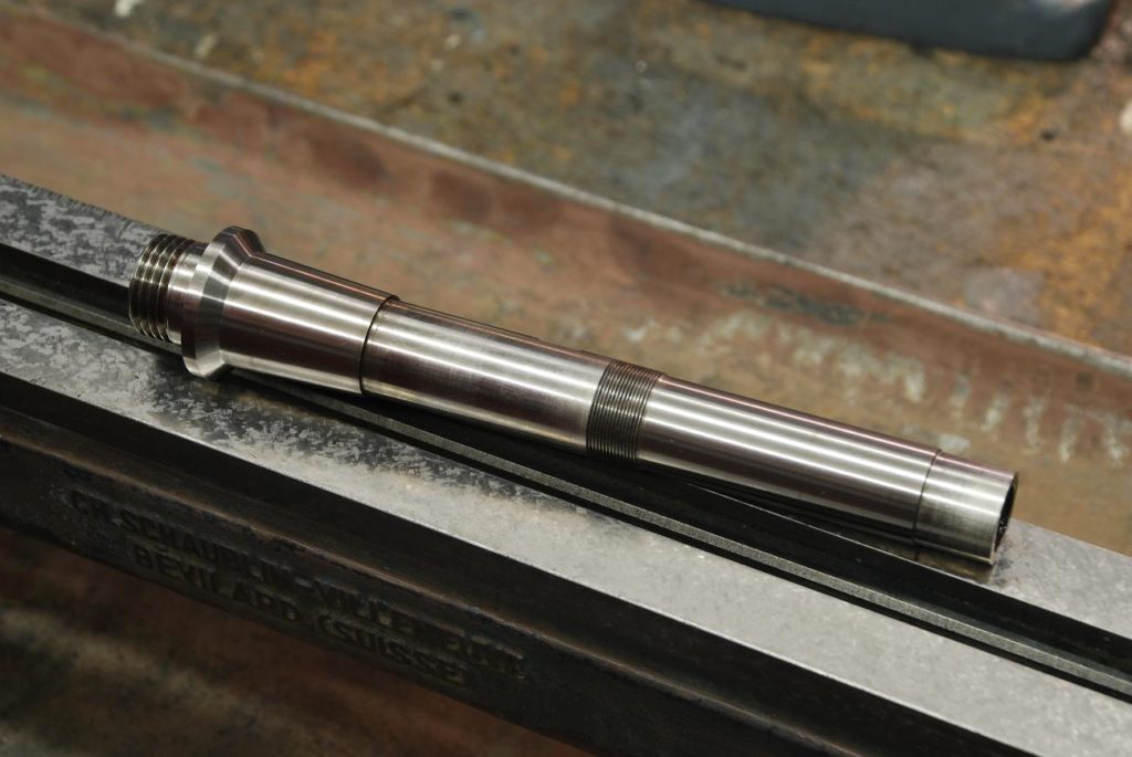
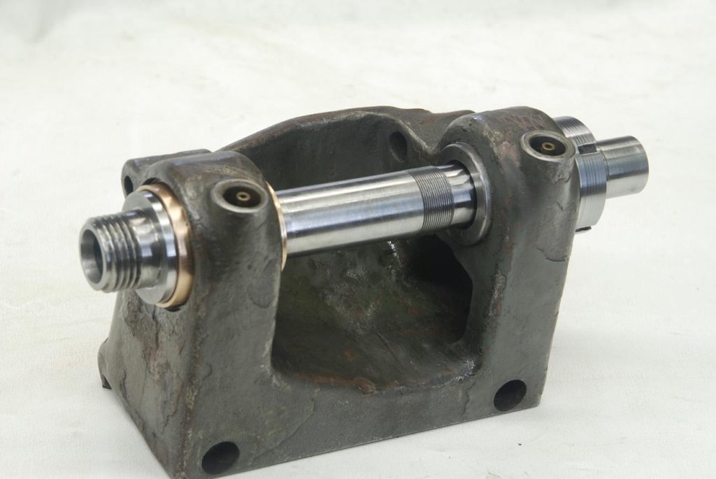
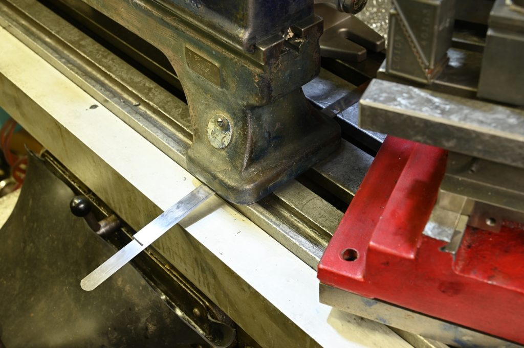
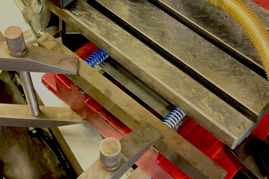
The finished shaft sitting on the freshly scraped bed
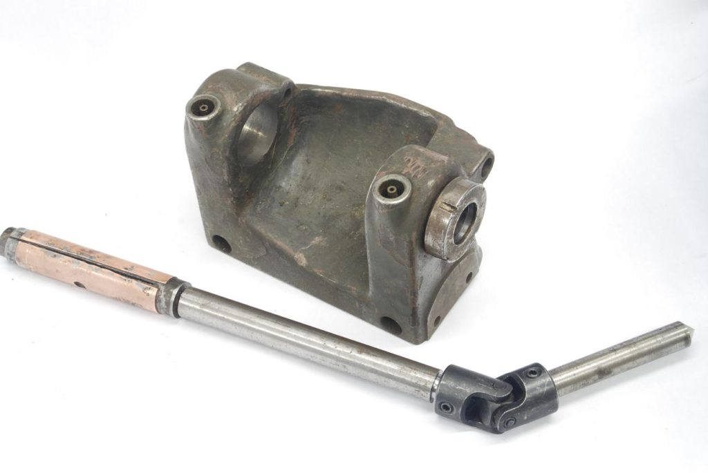
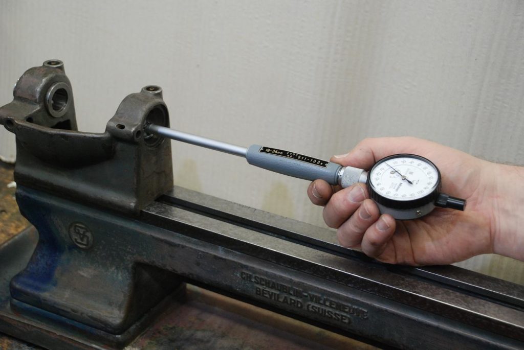
the Outboard Tailstock Bearing.
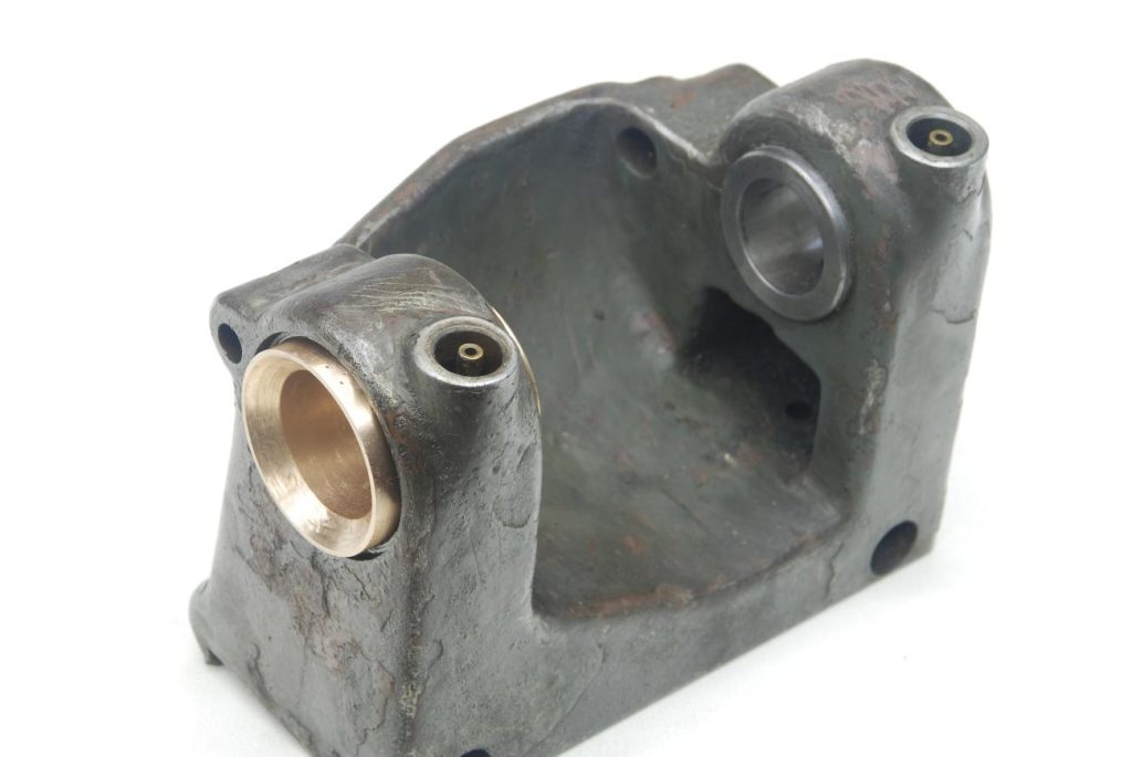
The next foothill to climb Is he a board headstock bearings.
This arrangement is a tapered bore in the headstock needed with a hardened tapered plane bearing That meets with the straight section of the spindle shaft.
The plan is to secure the bearing into the taper, and using a lap very close to the finish size of the shaft, lap the bearing to perfect a perfect cylindrical shape with a fine finish
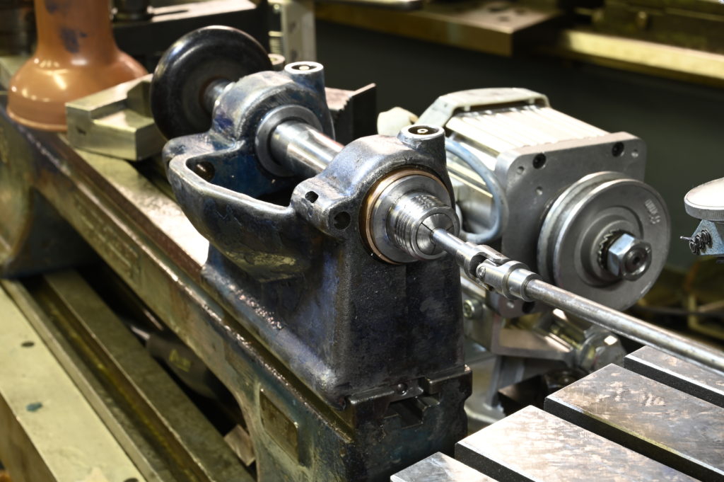
I’m starting with the lap used on the tailstock as it is the correct diameter. I’ve added a universal joints so that I can drive the lap from an electric drill. Remember with lapping, one of the work or the lap should float
Lapping is underway
Pretty good results, however as this is a rotating bearing and a critical part of the machine, I wanted to do a second round of lapping with 1000 grit.
You can’t just switch grips with the lap as the previous script is embedded in the lap. To change grits, I needed to remove the old copper and essentially remake the lap
Here we are with the lap redone. It’s been turned to size and lapping of the bearing in situ continues
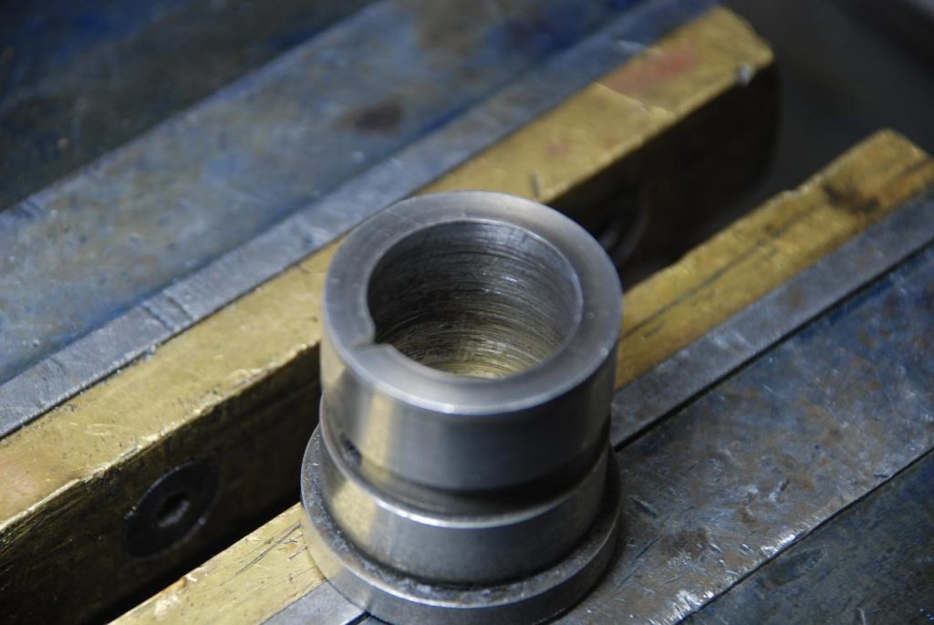
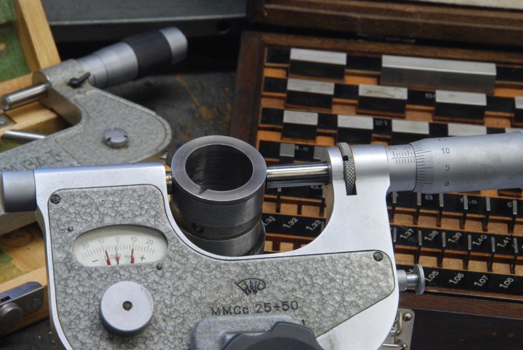
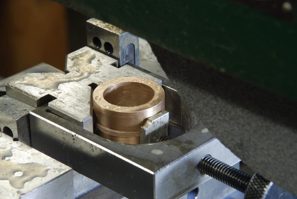
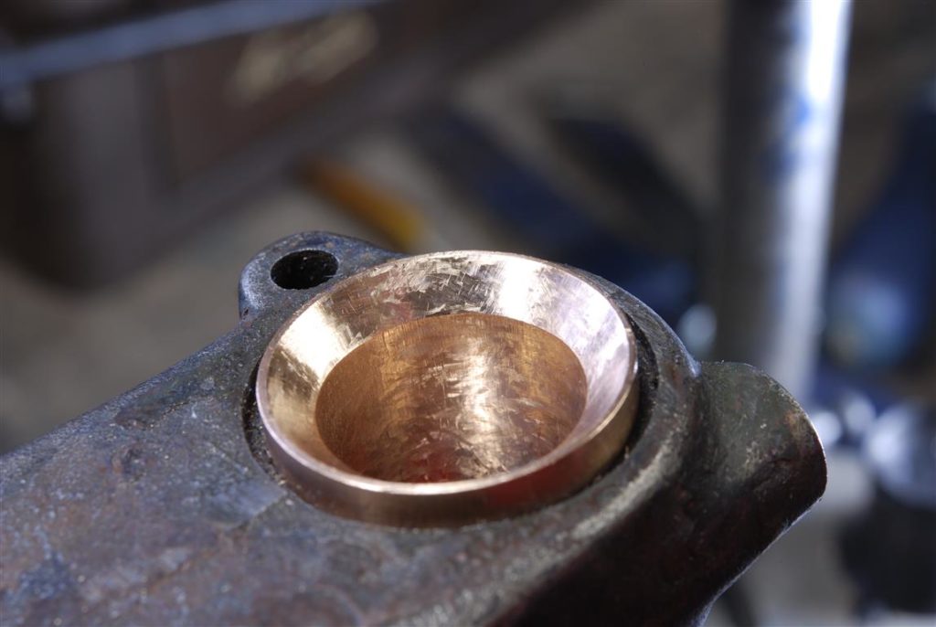
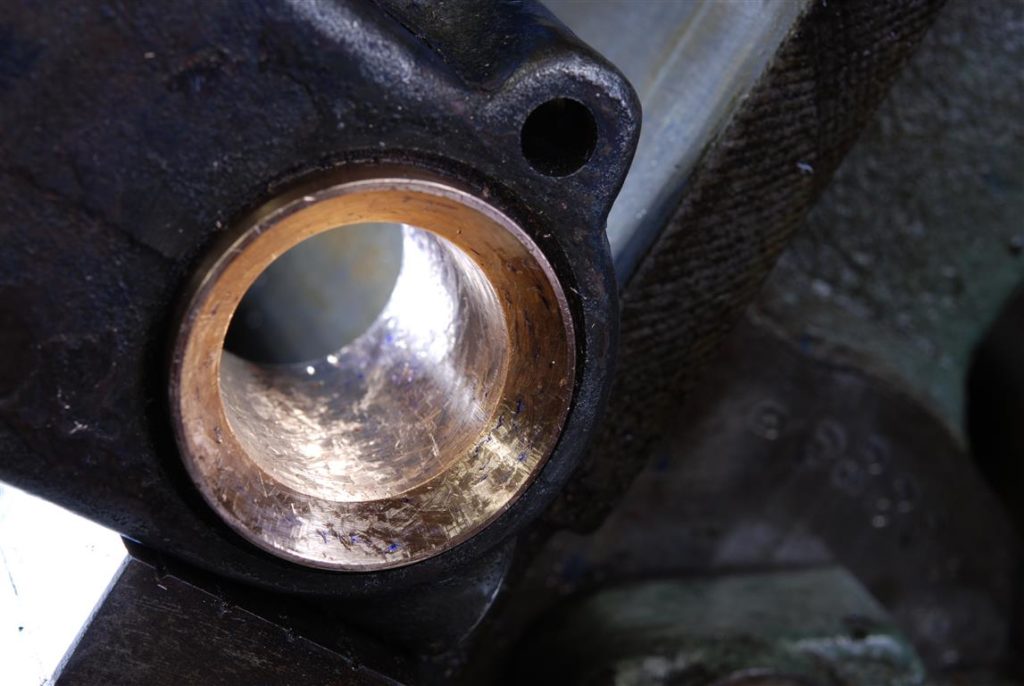
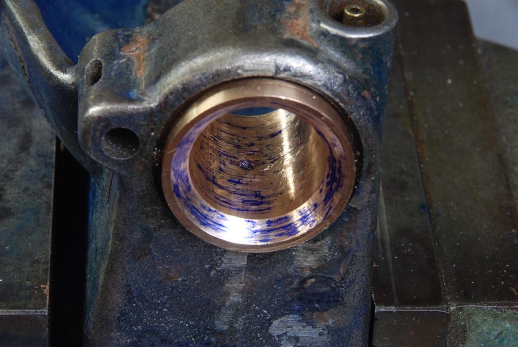
Here is a shot of the internal diameter of the bearing.
The Inboard Bearing
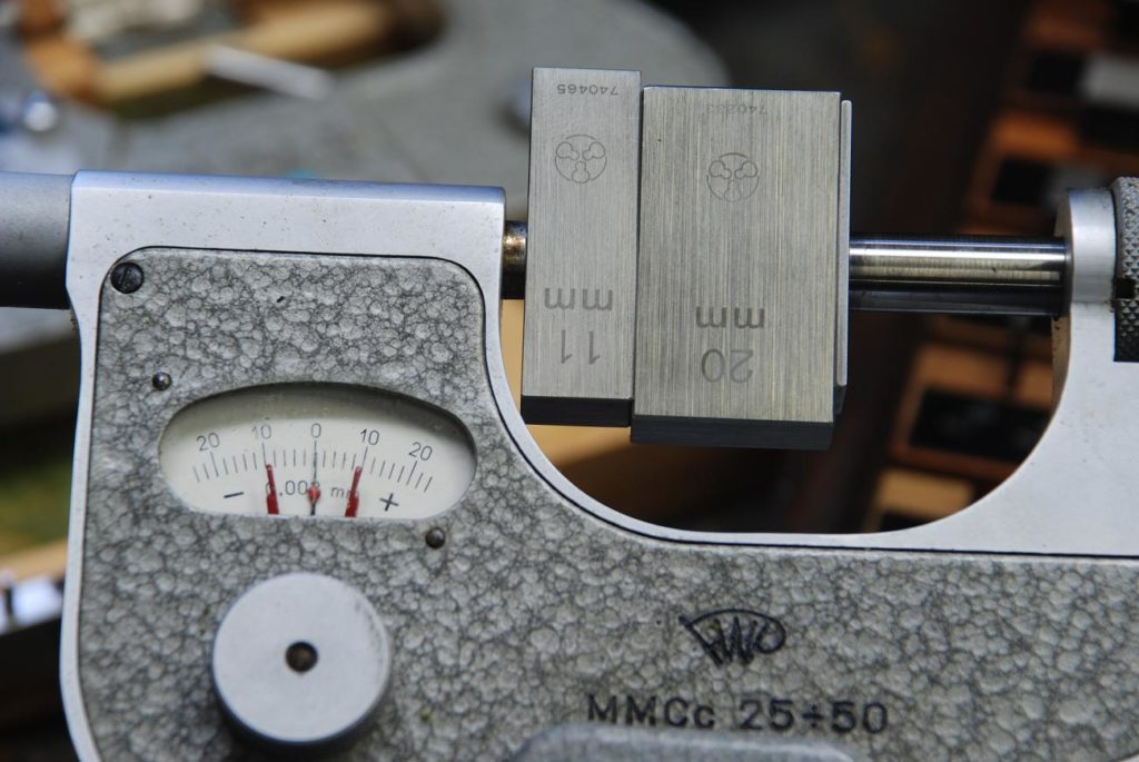
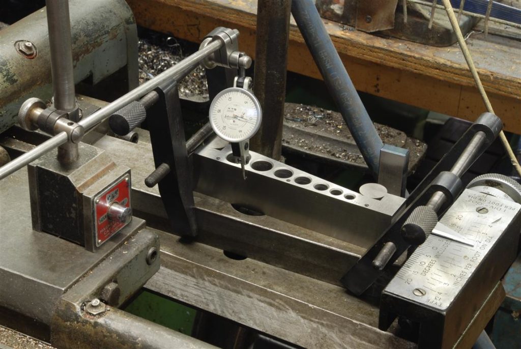
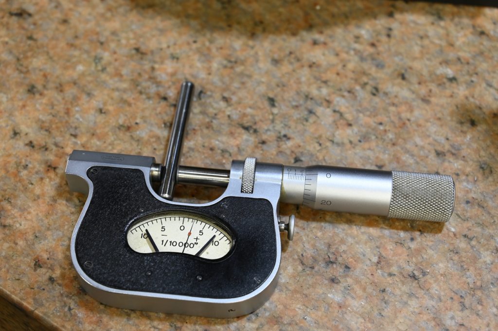
As the inboard bearing is a press fit into the headstock casting, and interference fits require a fair bit of accuracy to get the right, I put some effort into measuring the old bearing using an indicator might and gauge blocks.
an indicator mic is a super accurate way to measure
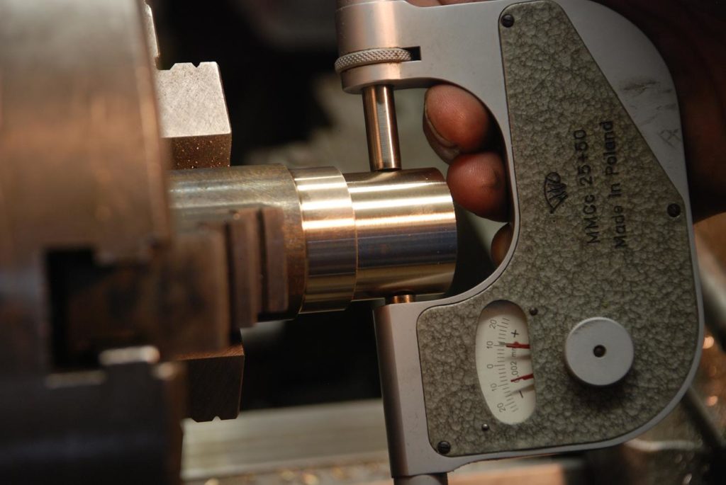
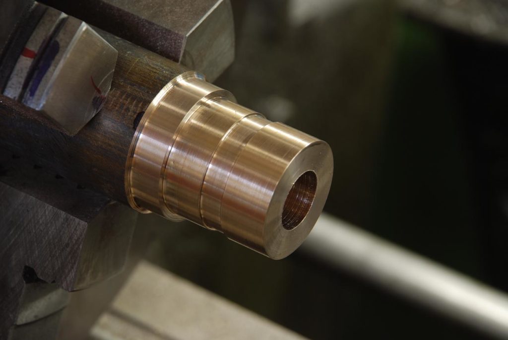
After getting the outside diameter spot on, I turned the oil path groove
And parted the work off
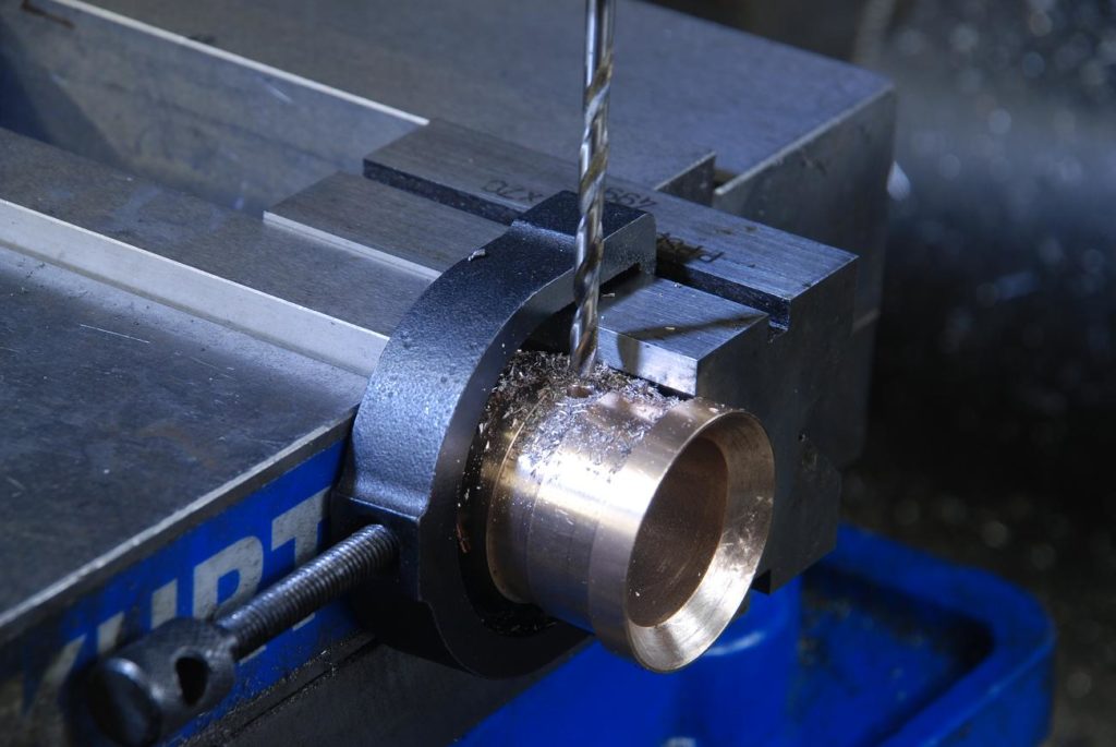
The oil passage hole was drilled….I’ll skip over the internal taper turning of this bearing for the time being but will pick it up later
Left end of this bearing acts as a thrust bearing against a caller mounted in the pulley. As such, I wanted it to have an excellent finish as well as be square to the turned axis of the bearing. A quick trip to the surface grinder made this an easy task
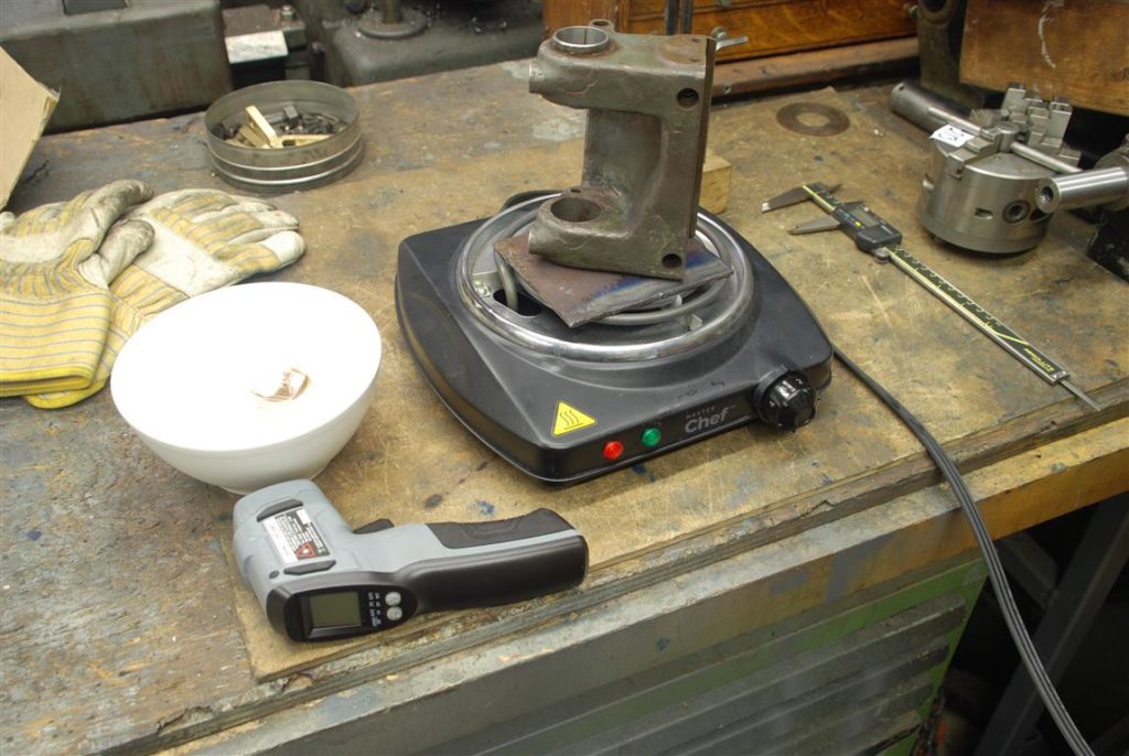
It’s a wonderful thing when you can assemble interference fits by heat. The outside diameter is warmed and in theory its mate drops right in. Here’s my setup with the headstock casting warming on the plate, the bearing a nice and a digital thermometer to know what’s what.
The theory is sound, however the amount of expansion you get is linearly proportional to the size. In other words a four-inch workpiece over a given temperature differential will change size 4 times as much as a one-inch workpiece. I find with bearing diameters around this size it’s a bit hit and miss whether or not you will generate enough clearance between the parts to let things just drop in place
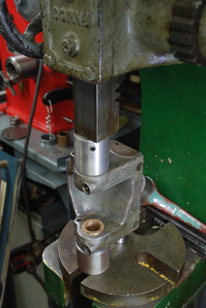
in this case despite my best efforts it was a fail. The bearings got halfway into the casting and froze up.
Not a big deal as the interference is not that great and it’s an easy press fit. One press fitting, to apply lubricate the pressing
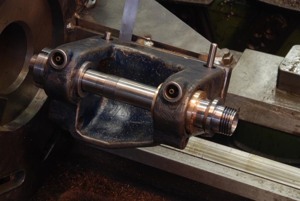
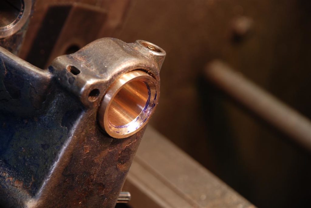
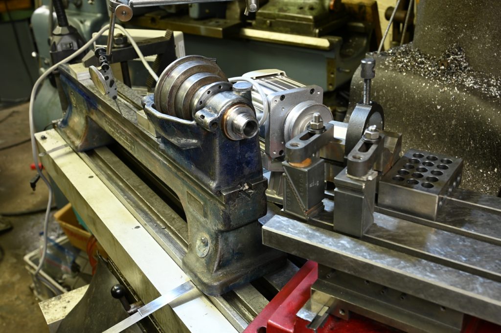
Just for fun, I put things together to see how they look.
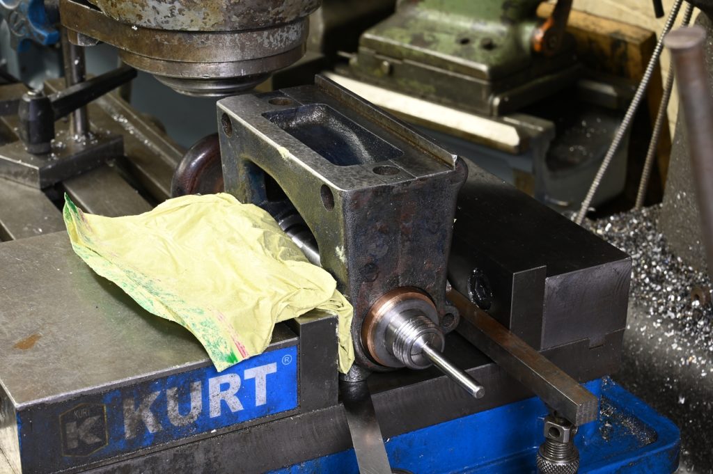
The plan all along has been to scrape the bearing into a perfect fit with the shaft
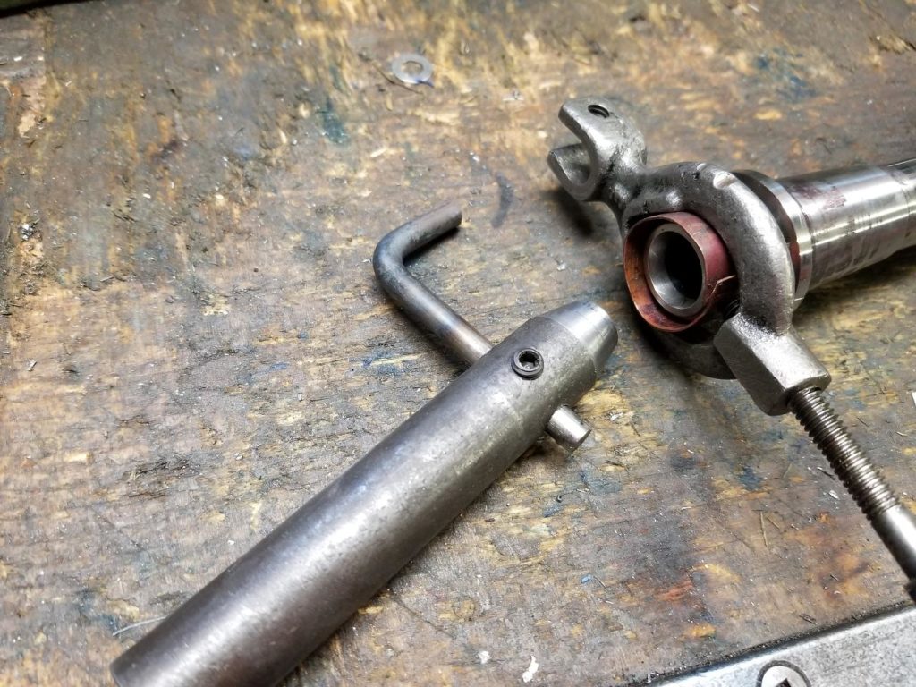
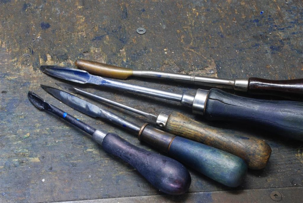
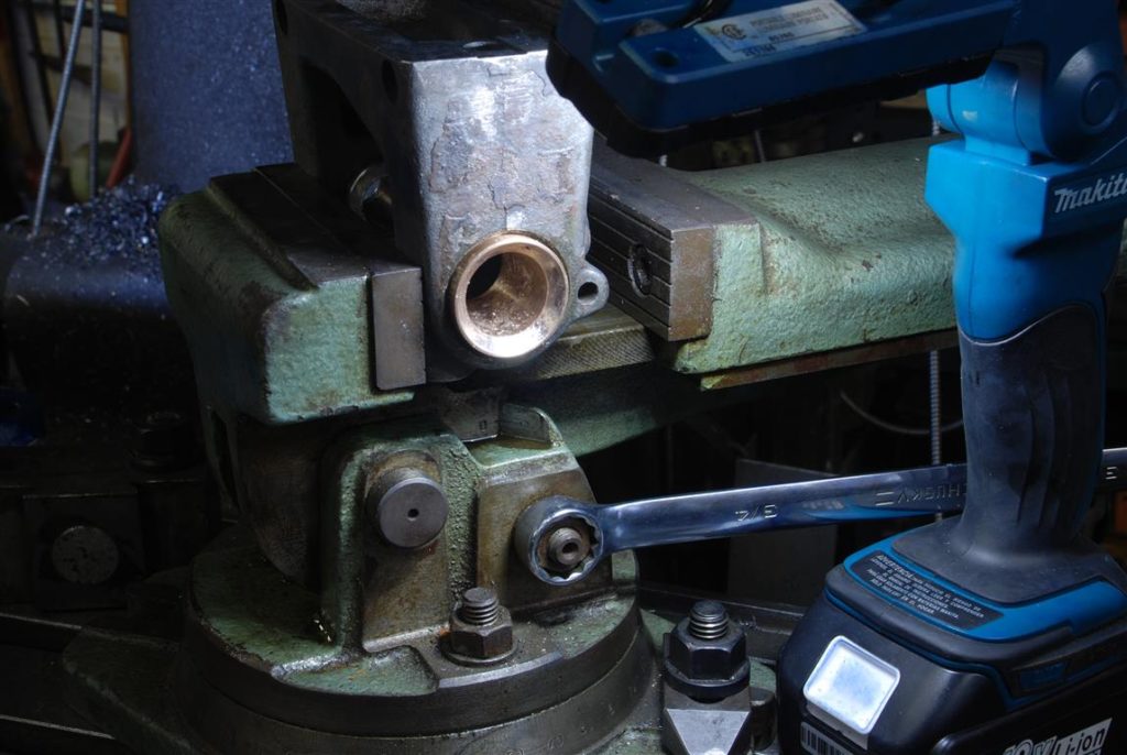
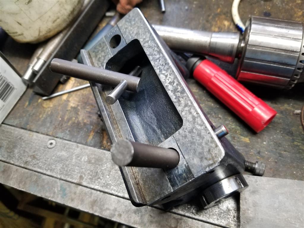
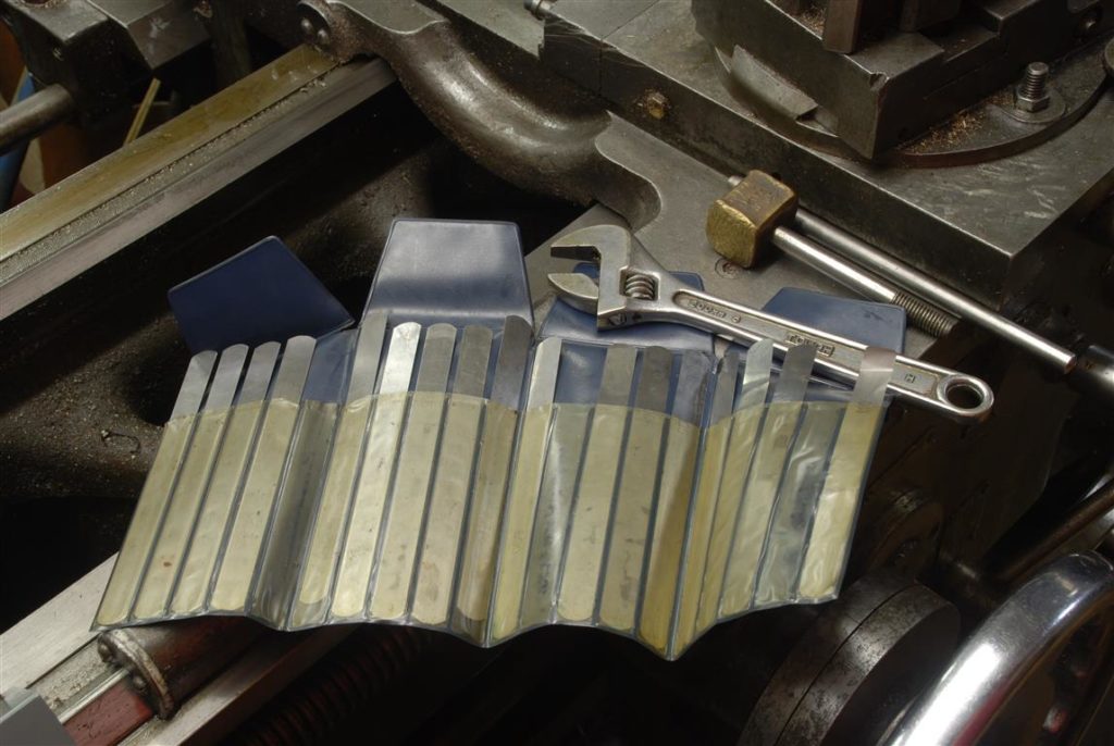
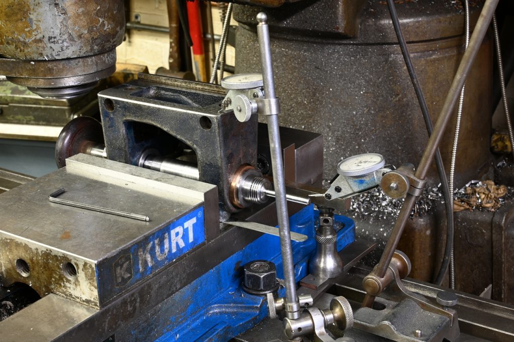
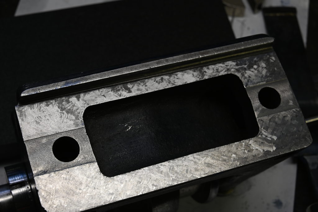
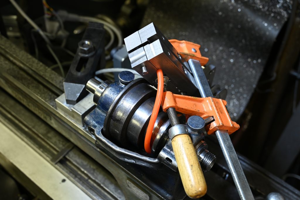
This photo shows a collection of internal bearing scrapers. Bearings scraping is Really supposed to be done on split bearings where the services are fully accessible. trying to scrape into the bore presents its challenges however is doable
A few photos showing some progress. the process was too snug the outboard bearing so it was a close sliding fit on the shaft, then blue the shaft and use it to print on the bronze bearing
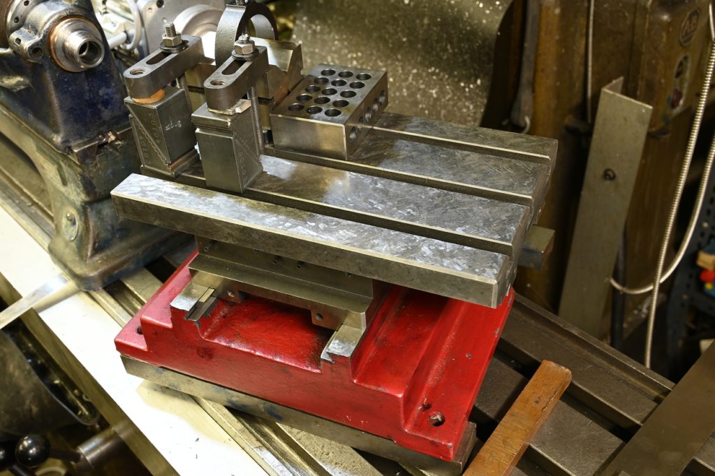
A swivel vise as shown in the photo is a huge help for this type of work.
Failure
The dreaded “F” word.
After Several sessions of scraping, I eventually could no longer deny that I wasn’t getting anywhere. I was only getting prints on the top of the 3° taper section. I just had no way of knowing whether I was One hour or one month away from making contact all around the 3° taper. Eventually I could no longer take it, concluded this approach failed and threw in the towel
a Revised Approach
What to do. The problem clearly was that the finish position of the lap out board bearing was not aligned with the headstock casting inboard bearing bore. This is the only logical conclusion as I knew that my bronze bearing was concentric ( ID and OD turned at one setting)
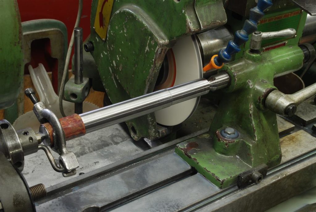
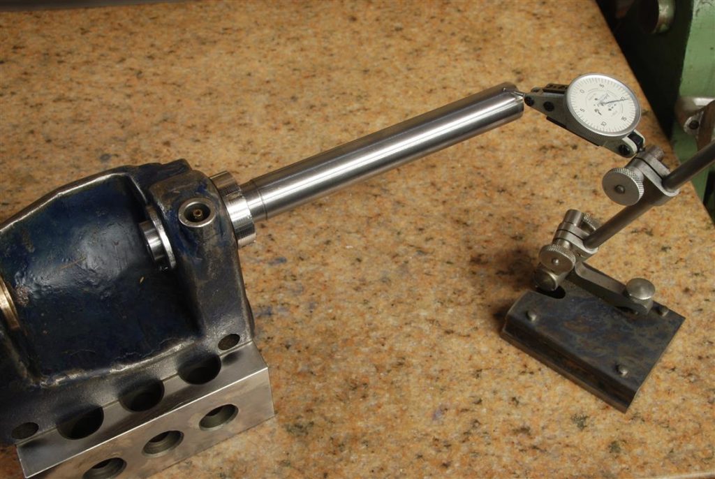
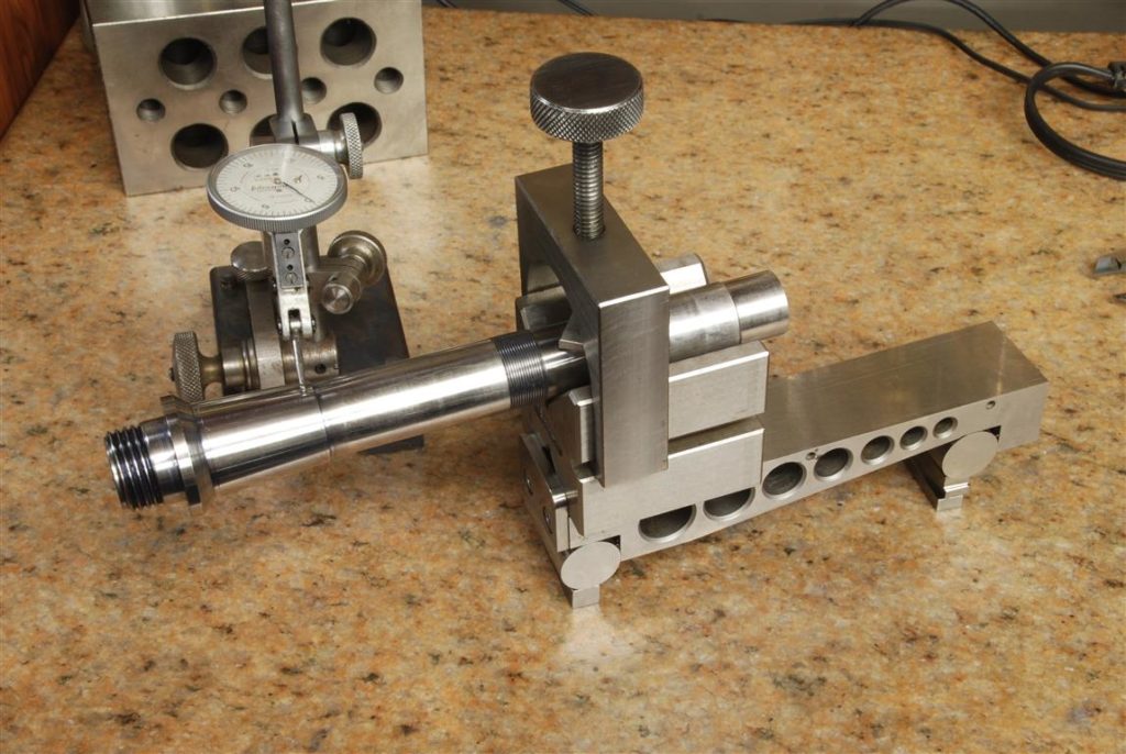
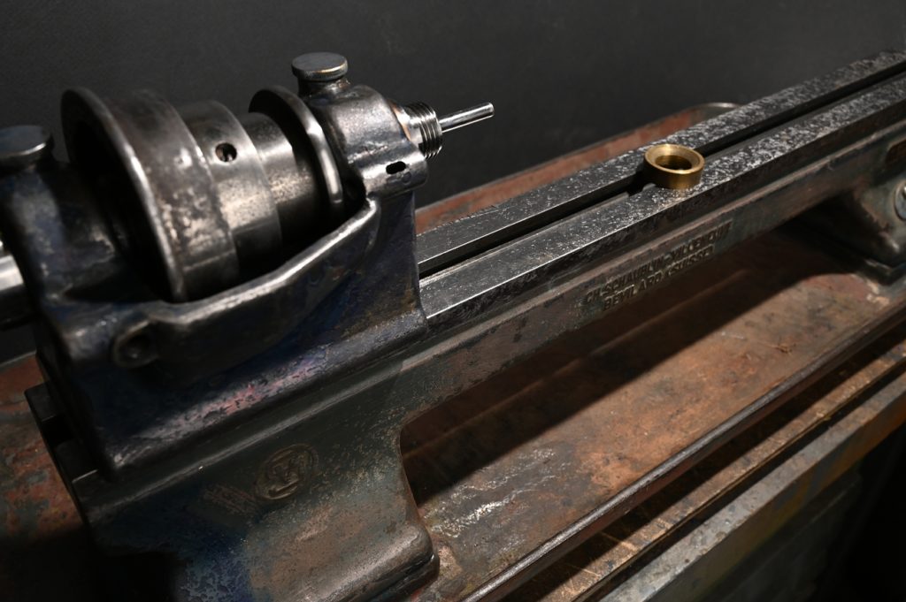
How I decided to proceed was to grind a very accurate test bar but I could hold in the outboard bearing
To get a good level of accuracy, the first thing is to grind in situ a center for the bar
The test Bar is carefully ground and holds the 10th over its length. One end is ground to be a precision fit such that the outboard bearing can be tightened to clamp it into position
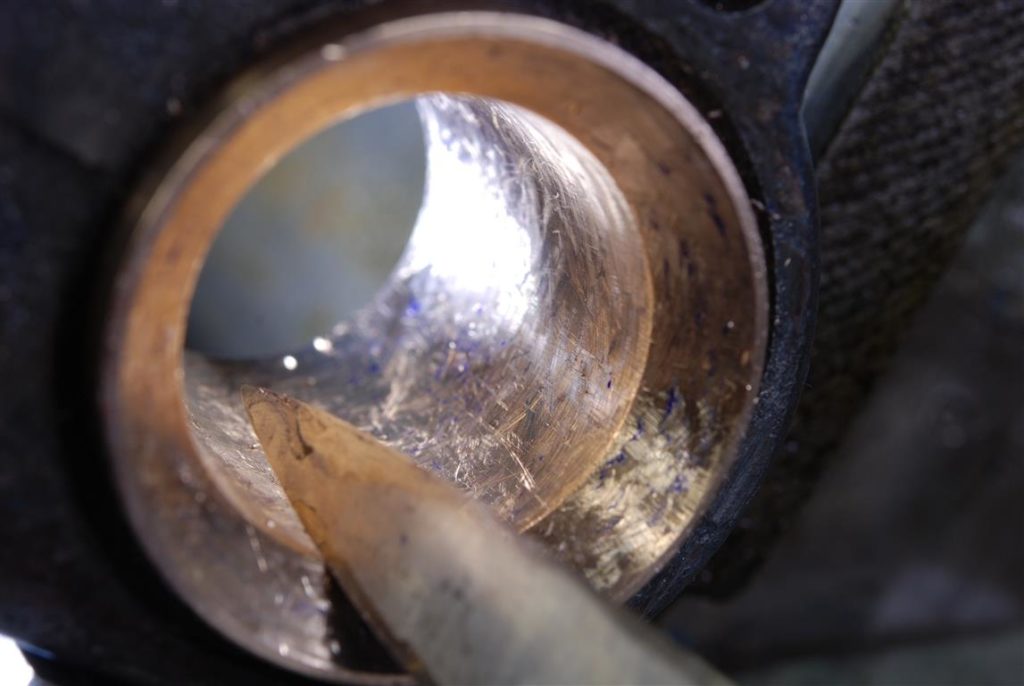
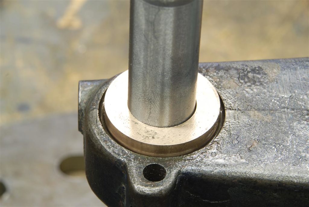
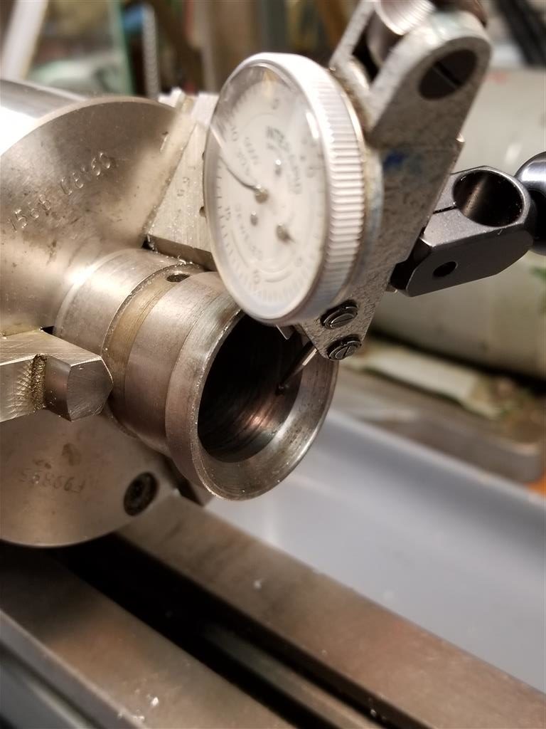
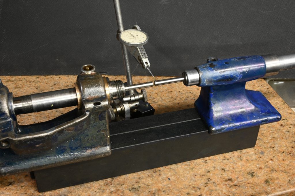
With the test part held in the outboard bearing, it’s a bit shocking how misaligned the bronze bearing is. In the photograph it looks like it’s touching at the top, however while it’s very close to it’s not actually touching ( easily proven by seeing the light is coming through)
some head scratching an investigation
I assumed the OEM bearing would be perfectly concentric however tto extricate myself from this fellow, everything needed checking.
With the OEM bearing held in a lathe ( coincidently another Schaublin 70 I checked constant custody by comparing the OD to the ID
naturally, held in the three job, there is going to be some run out on the OD however the test is to compare this run out to any right out of the ID
I was really surprised to find there was about four thou run out. I don’t know how these headstock sport manufactured, however this fact suggest that the bearing was pressed into the headstock and then finish ground in relation to the base of the headstock such that the headstock bore locations were essentially irrelevant
The next test is to mount the taskbar in the bearing and see how it compares to the bottom of the headstock. it was out five thou over the length of the taskbar. These two errors at added up and the result is my current situation of a head start in board bearing badly misaligned with the outboard bearing
Position relative to the bottom of the headstock is not troubling as this will get corrected by scraping. However It’s certainly not six hours of scraping to correct this, more like six months and in any event by the time it was corrected the shaft would sit too deeply into the bearing. Scrap the Mark I bearing and start over
I’ve got a plan ( everyone ducks for cover).
The idea is to create a fixture, mount the entire headstock and lathe, indicate the heck out of everything until it’s aligned, then bore the inboard bearing in situ
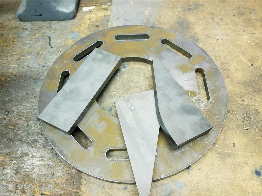
the raw parts for the fixture, burned out of half inch plate,
I came up with a scheme to hold the headstock to the fixture
The posts get threaded and then bolt to the fixture
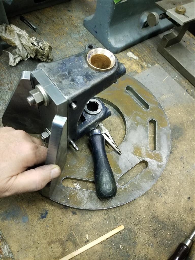
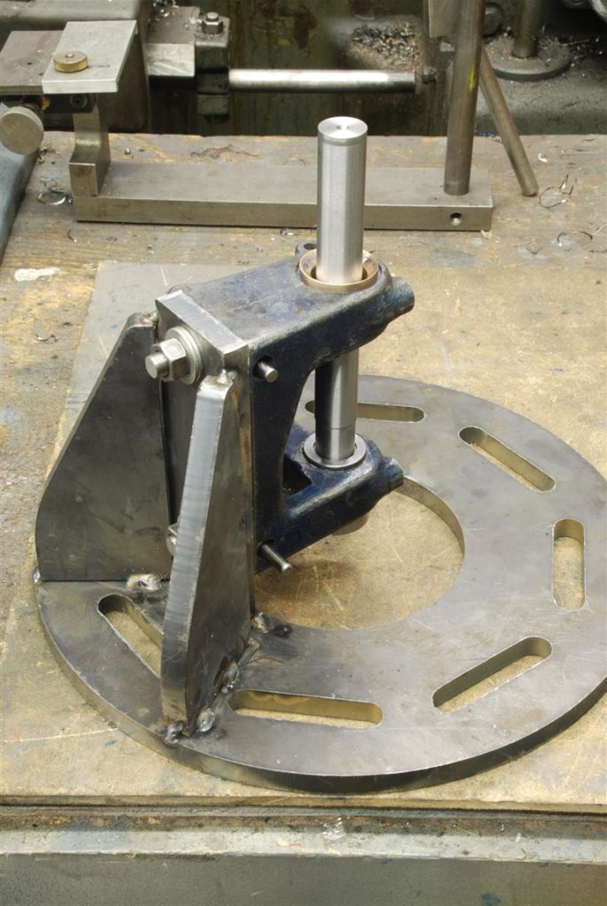
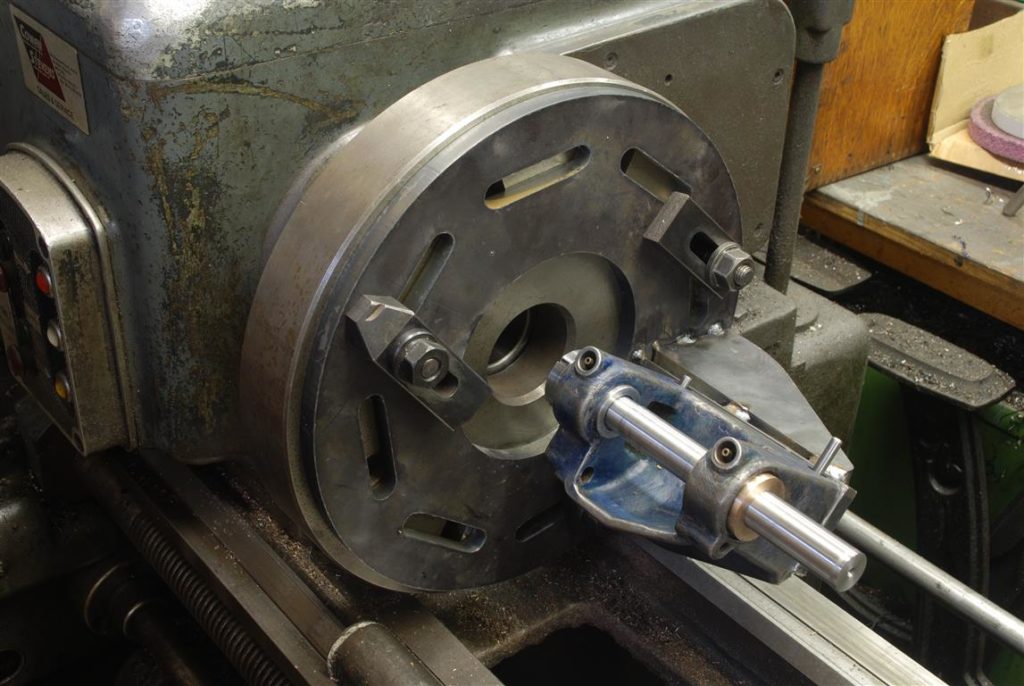
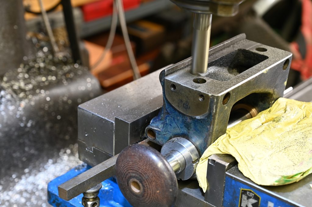
Here I am mocking up the fixture with the headstock mounted
Everything is welded. I went fairly light on the welding as firstly it won’t need much strength and secondly fixture plate can be reusable with all manner of things zip cut off and welded onto it
Now to the new bronze bearing
It’s turned and thrilled however the board is left straight and with Clarence relative to the taskbar
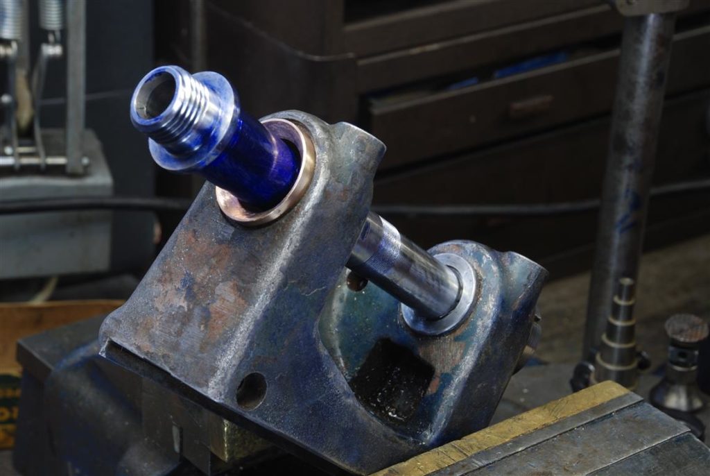
This shows the general plan. Note the taskbar is clamped by the outboard bearing and is not touching the bronze bearing
The taper on the shaft is double checked. It’s held like this as the cylindrical surface it’s clamped by is the only one that we know is concentric with the taper bearing section
But then the taper attachment is dialed in with the sign bars
Now the real fun starts.
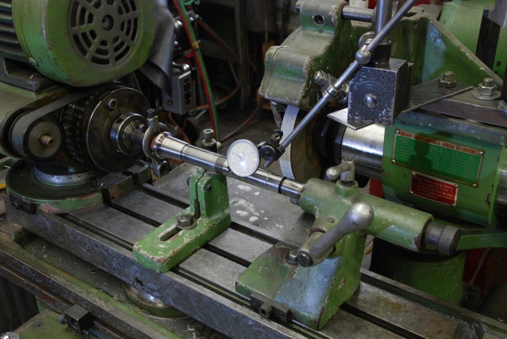
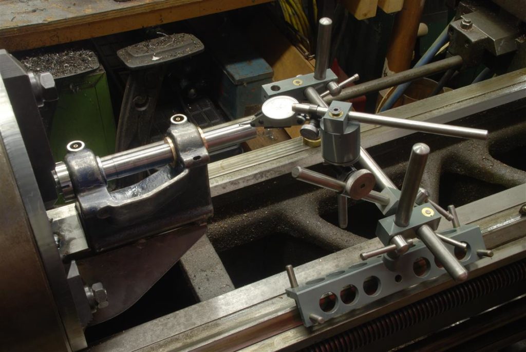
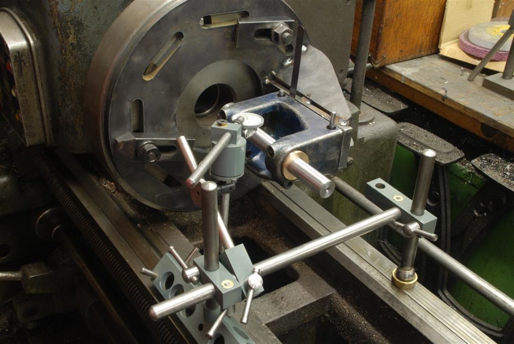
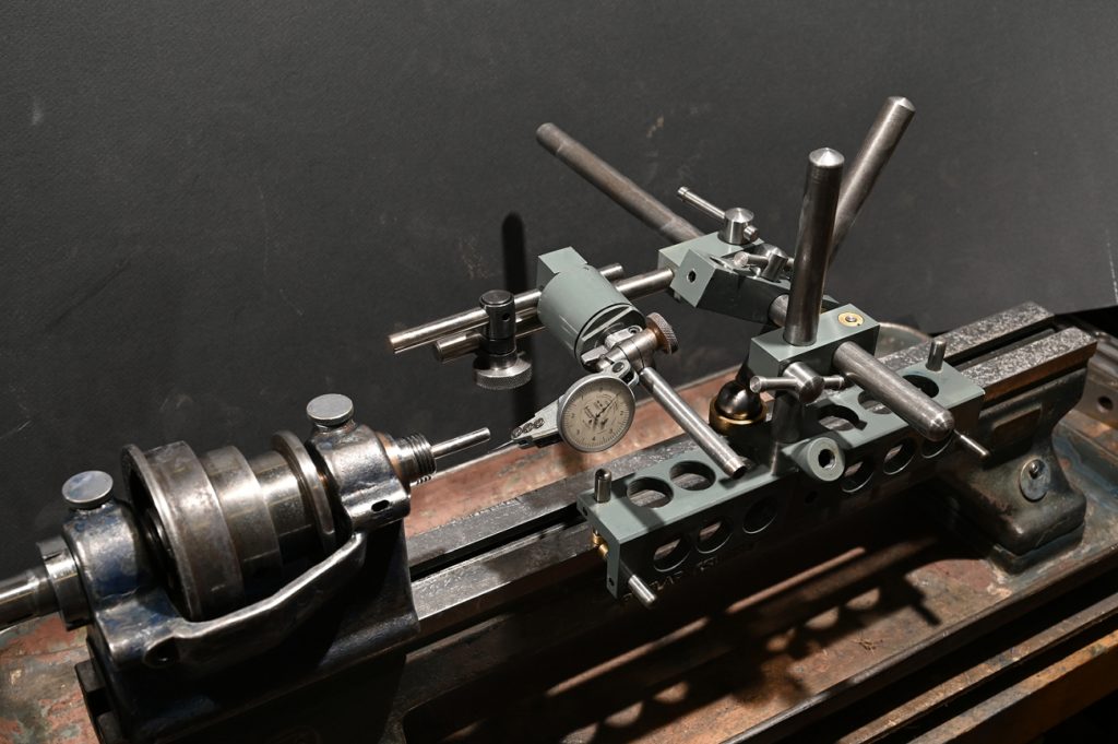
With the fixture, aligning it on the lathe is complicated.Its not a precision device, so first I have to make sure the test bare is square to the face plate in two planes (in other works parallel to but not necessarily aligned with the lathes axis).Then I had to centre it to the lathes axis.Because it’s a connected system, there was a lot of back and forth – change one thing and another moves slightlyThis took the better part of a morning as it just had to be right.
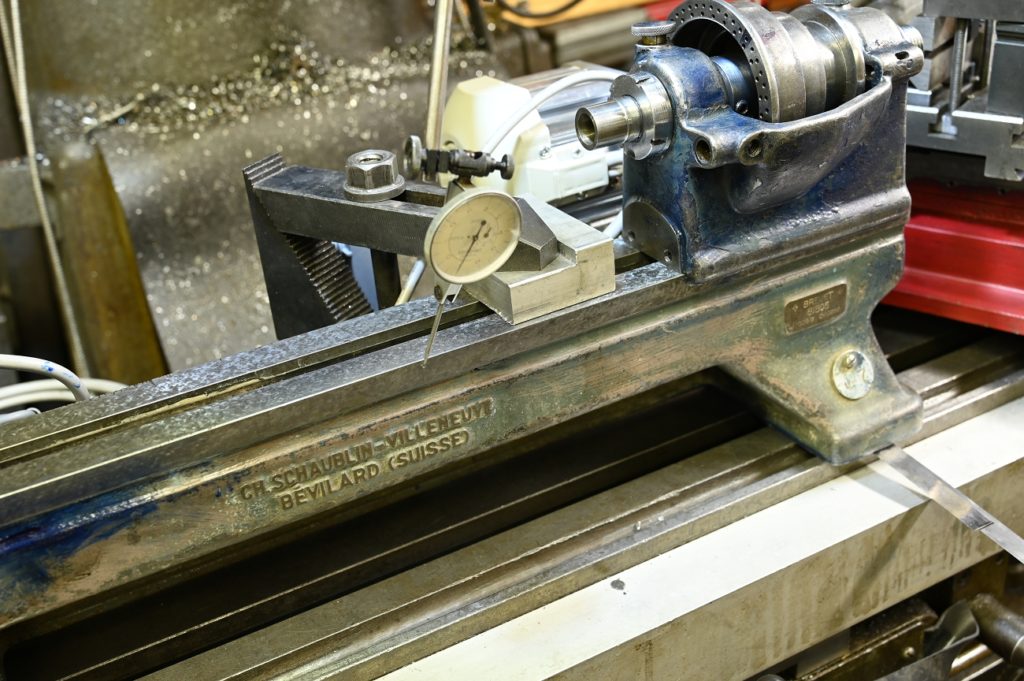
My machine tool alignment device (made for scraping) was perfect for this.The grey cylindrical thing the indicator sticks out of is a spindle itself (P4 AC bearings) so the indictor can be swung over what’s being measured
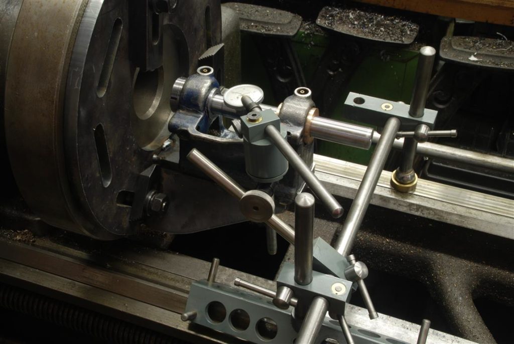
Keep in the mind the test bar is clamped the rear bearing and is not touching the bronze bearing.It represent/projects the true axis of the outboard bearing lapping ID….all this work is to set up the inboard bearing to bored inline with the outboard bearing
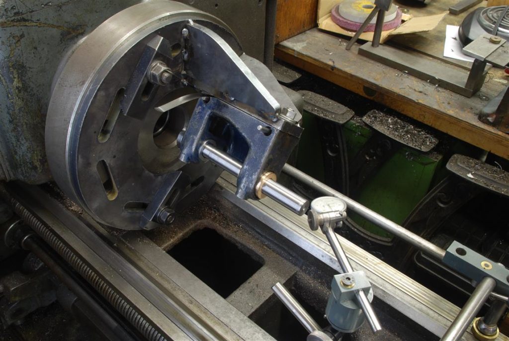
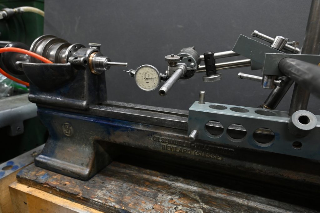
First the indicator is swept over this end of the test bar
Then over this end . I used as much of the test bar length as possible and obviously this test is measuring how closely to parallel the bar is too the lathes axis in one plane.
I’d loosen the bolts and shim one end until
I got readings within ½ a thou of the length of the test bar.Notice the shims under the end of the
headstock
This little pack of shims, hardened loose feeler gauges really, I picked up somewhere was perfect….
Then, I do the same with the headstock in this position – the second plan. If I get the test bar zeroed out in two planes, its parallel to the lathe’s axis
Parallel, but not yet aligned!Now I have to slightly loosen the face plates
bolts and tap it around until I get it perfectly concentric.Of course the back of the fixture isn’t as
flat as the faceplate so loosening said bolts puts the bar no longer parallel
with the lathe
This process was repeated from start to
finish many times, each trying for a more precise alignment, and when the bolts
kept tighter, and tapping smalling
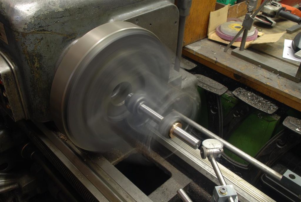
Eventually….success. everything is perfect over the test bar to ½ a thou.
I didn’t bother about counter weights, not needed. It’s a 5200 lb lathe and I went slowly – 70 rpm
Ready for turning. as I’m using a telescoping taper attachment, I reversed the fee to turn from the headstock to the tailstock
I worked very slowly, fine feed max .005 DOC as I did not want to apply forced that would have any chance of disturbing the setup. Between cuts, I cleaned the shop.
A tricky bit, is that on the 3 degree taper a .001 difference in diameter with cause a .01” difference in axial position
I got the 3 degree taper close. Then I’d insert the shaft and measured with a caliper and a loupe assisted eyeball how much further in axially it had to go
Here for example, if it needs to in 400 thou more, I need to take 4 more 5 thou DOC passes. Using that approach I got the 3 degree taper about right. Measuring the axial position of a taper is tricky – you’d need to make gauges or insert a ball and measure its depth etc. Measuring the axial position of two tapers to each other needs some special gauging or a wizard’s hat. l
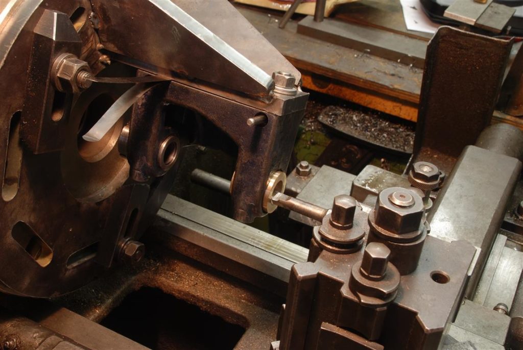
Making the leap of faith on how far to take the 3° taper, I did a fine finishing cut, then worked on the 45° taper
With a thick coat of blue on the shaft, I kept checking until I got the first
I then hand scraped, Without disturbing the setup in case I had to turn some more, a 45° taper until good contact was made on both bearing surfaces
Lorem ipsum dolor sit amet, consectetur adipiscing elit. Ut elit tellus, luctus nec ullamcorper mattis, pulvinar dapibus leo.
Lorem ipsum dolor sit amet, consectetur adipiscing elit. Ut elit tellus, luctus nec ullamcorper mattis, pulvinar dapibus leo.
Lorem ipsum dolor sit amet, consectetur adipiscing elit. Ut elit tellus, luctus nec ullamcorper mattis, pulvinar dapibus leo.
Lorem ipsum dolor sit amet, consectetur adipiscing elit. Ut elit tellus, luctus nec ullamcorper mattis, pulvinar dapibus leo.
Lorem ipsum dolor sit amet, consectetur adipiscing elit. Ut elit tellus, luctus nec ullamcorper mattis, pulvinar dapibus leo.
Lorem ipsum dolor sit amet, consectetur adipiscing elit. Ut elit tellus, luctus nec ullamcorper mattis, pulvinar dapibus leo.
Lorem ipsum dolor sit amet, consectetur adipiscing elit. Ut elit tellus, luctus nec ullamcorper mattis, pulvinar dapibus leo.
Lorem ipsum dolor sit amet, consectetur adipiscing elit. Ut elit tellus, luctus nec ullamcorper mattis, pulvinar dapibus leo.
Lorem ipsum dolor sit amet, consectetur adipiscing elit. Ut elit tellus, luctus nec ullamcorper mattis, pulvinar dapibus leo.
Lorem ipsum dolor sit amet, consectetur adipiscing elit. Ut elit tellus, luctus nec ullamcorper mattis, pulvinar dapibus leo.
Lorem ipsum dolor sit amet, consectetur adipiscing elit. Ut elit tellus, luctus nec ullamcorper mattis, pulvinar dapibus leo.
Lorem ipsum dolor sit amet, consectetur adipiscing elit. Ut elit tellus, luctus nec ullamcorper mattis, pulvinar dapibus leo.
Lorem ipsum dolor sit amet, consectetur adipiscing elit. Ut elit tellus, luctus nec ullamcorper mattis, pulvinar dapibus leo.
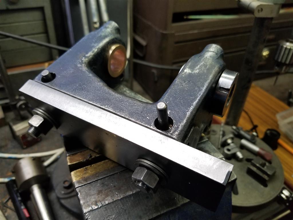
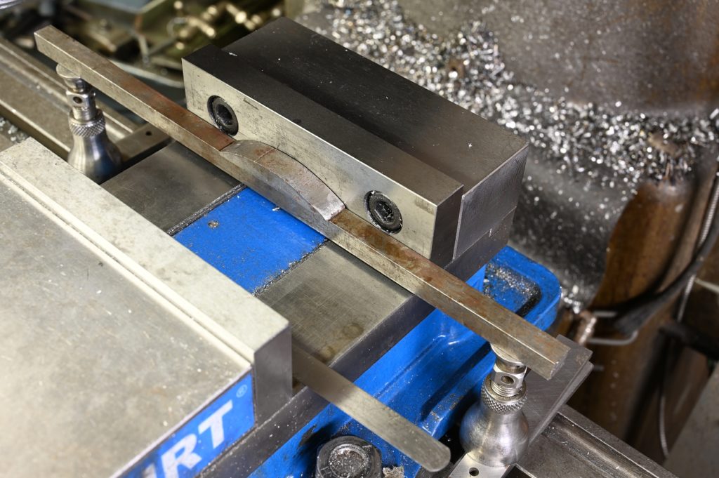
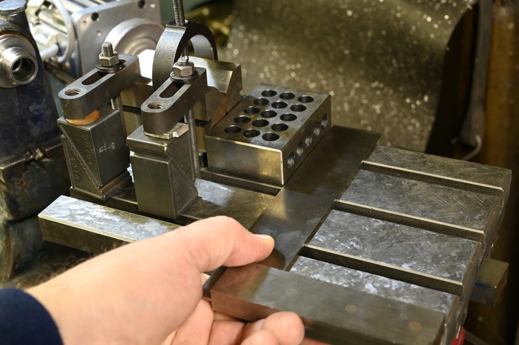
Now were are getting down to the final determinants of accuracy with the spindle. Its good practive to prove the tools used to make sure they are not introducing problems.
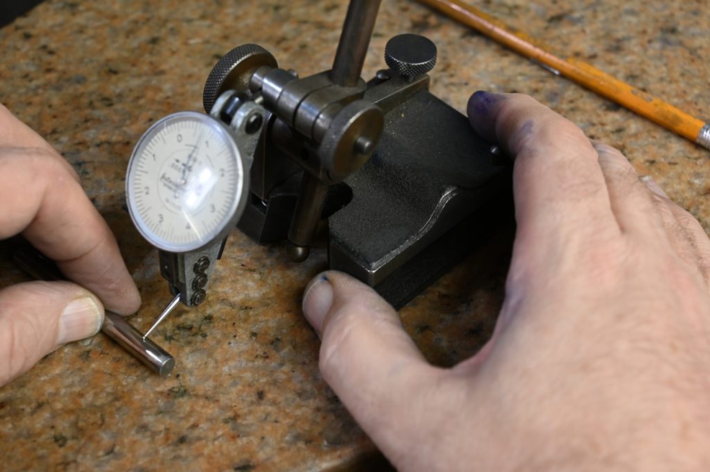
The pins are checked for straightness and diameter
and the parallels checked for parallelism
As a result of milling the HS, it will be the lowest item and the tailstock brought down to it.
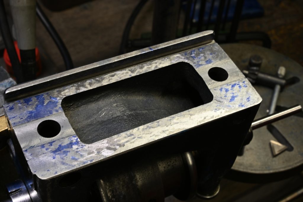
We are first going to scrape the bottom of the HS (the X/Z plane). The goal is to have this plane parallel to the headstock spindle.
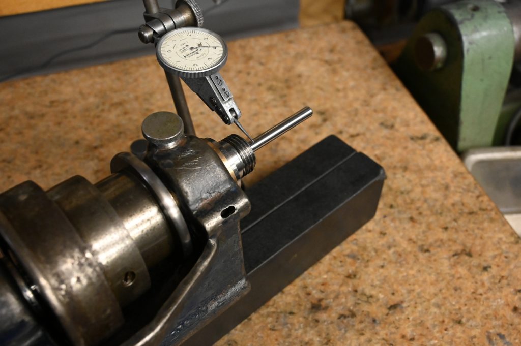
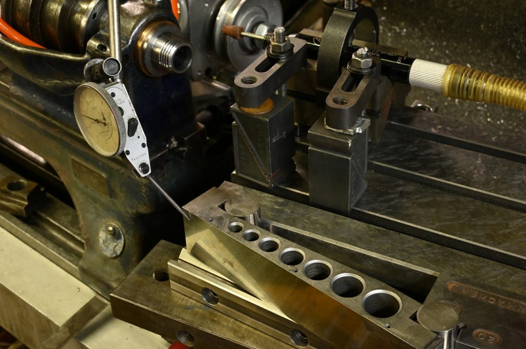
We have no direct way to measure that, so will hold pin in the headstock and indicate it
However, we have to be a bit clever because the spindle nose is not guaranteed to be concentric with the spindle shaft bearing (as I reground the shaft OD).
If you were a lathe manufacture a ground, super accurate test bar could be mounted in the spindle. This is for expediency, however some people have developed the that you have to have a test bar – False!
You don’t need a test, and there is actually a superior to measure. Superior in that any misalignment between the bars mounting to the spindle doesn’t matter
Al that matters is that the pin is straight and a consistent diameter. It does not matter if its held accurately, you could use a three jaw chuck if you like.
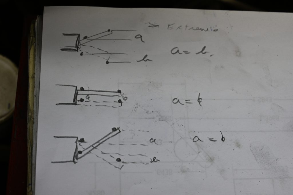
The way it works is, indicate close to the spindle nose. Then indicate away from the spindle nose. Write down the readings. We’ll call the difference “a”.
Then rotate the spindle 180 degrees and repeat; the difference we’ll call “b”
When a = b, the spindle rotational axis is perfectly aligned with the plane it was measure from (the surface plate which is the same as, i.e. parallel to, the bottom of the headstocl
I made table and had page after page of entries as I scrape the bottom in.
Its important that only the ends are bearing while you are woking toward alignment so there can be no rocking that will produce false measurements
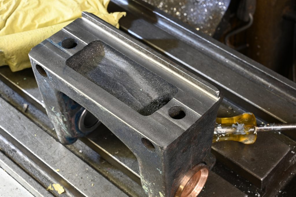
Hollow out just enough to get good prints. As perfect alignment is approached, the the hollowing out disappear so there is full contact
Now the process gets repeated for the X/Y plane (vertical). This is a bit more complex as we can’t really do this on the surface plate so will use the lathe bed and the alignment tool
Lorem ipsum dolor sit amet, consectetur adipiscing elit. Ut elit tellus, luctus nec ullamcorper mattis, pulvinar dapibus leo.
Painstakingly do the interrelations until a=b
The final big job (there’s a few other smaller ones) on the headstock is to regrind the the spindle nose taper.
As a general rule, don’t regrind the spindle unless there is a reason to. For example, if its undamaged, and all you are doing is replacing bearings, its likley not necessary.
However in the case, since I ground the spindle shaft OD, we need to grind the ID with the shaft rotating in its bearing to ensure concentricity.
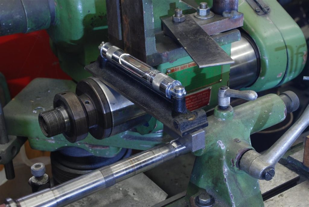
I used the mill table and first indicated the front of the bed to be parallel with the mill tables motion. The headstock has been positioned at the far right end of the bed vs its usually spot on the left end.
A mini mill X/Y table is positioned on the mill table. I scrape this table so it will provide perfectly smooth and accurate motion for the grinder
Using a height gauge and a pin mounted in the spindle nose, I compared the height of the grinder’s spindle and the lathe spindle. Tapers must always be machine on centre. I then shimmed the bed so the two were the same height.
The the bed is indicated and made parallel to the mill table’s motion
A temporary motor is rigged and a round belt made up to connect the two. Obviously its a flat belt pulley, however round is sufficient for the tiny forces grinding imposes
Next, the V block holding the grinder is made square to the mini mill table.
Then, with a sine set at the correct angle, I adjusted the mini mill table using an indicator until the sine bar was aligned with the mill’s table motion.
This should give us an axis of motion for the grinder at the correct angle to the lathe spindle
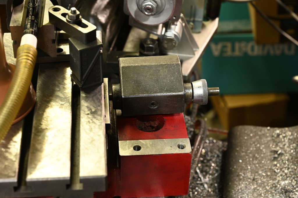
now I need to control the depth of cut – the mini mill tables Y axis. I machine an adapter (not visle) that let mount a lathe micrometer stop on the mill’s base.
To eliminate backlash in the infeed, I used some die springs on the mini mll Y axis acting the opposite direction o the lathe carriage stop
I slide the headstock back an bit got a small mag chuck in the bed ways. To this I mounted a block I’d drilled at the right height to take a diamond dresser.
The last bit was to rig up the lever mechanism from a lever action cross slide ( a mford I believe) to create a way to move the mini mill table along its X axis. I didn’t capture this with a photo, however it can be seen in the video of the process.
checking the results of the operation are shown in the video