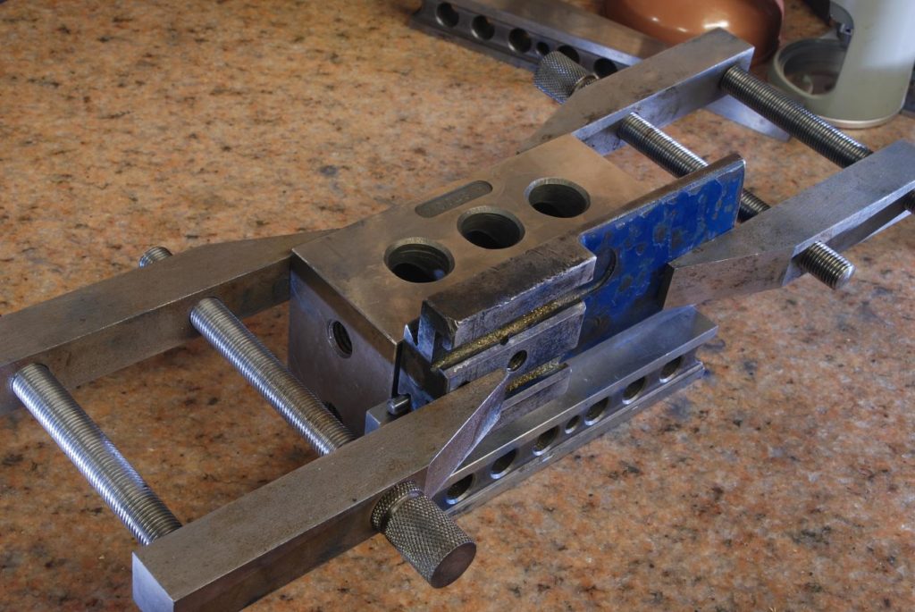
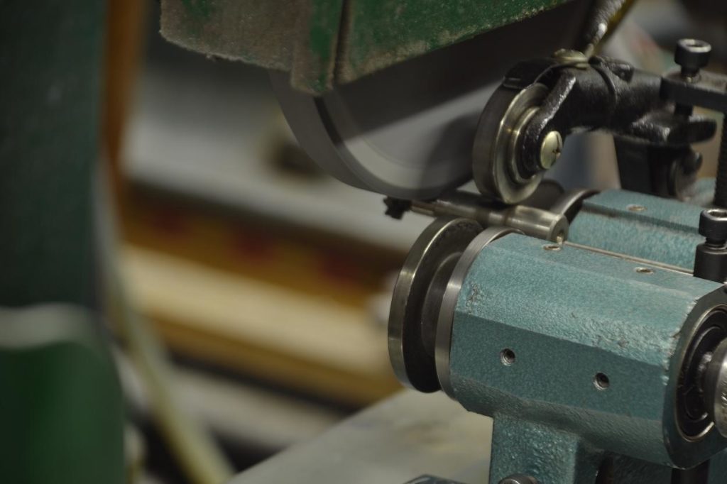
Like the rest of the lathe, the slide rest needs a complete rebuild
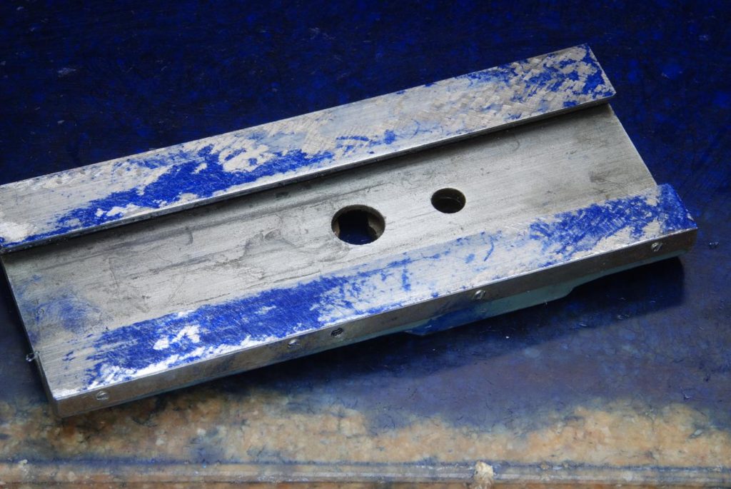
Lots of visible wear and scoring
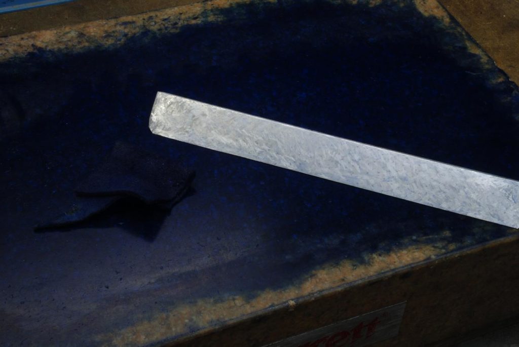
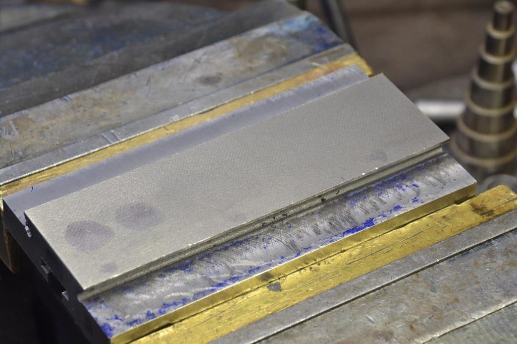
the logical starting point are the horizontal surfaces of the female dovetail as they can easily be printed on a surface plate. The first print using a fairly heavy coat of blue
Working away at it
In not too much time we get complete coverage and then it’s a matter of fine scraping for a high density of bearing points
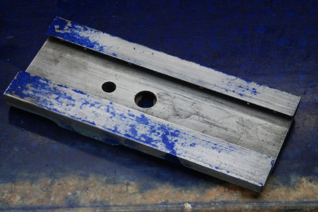
With the female of dovetail complete, it’s used to print the horizontal surfaces on the Mail dovetail
Moving up pancake stack, scraping the next these
And it too is soon complete
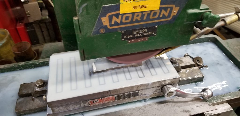
As I have a surface grinder, it made more sense to grind rather than scrape the surface.
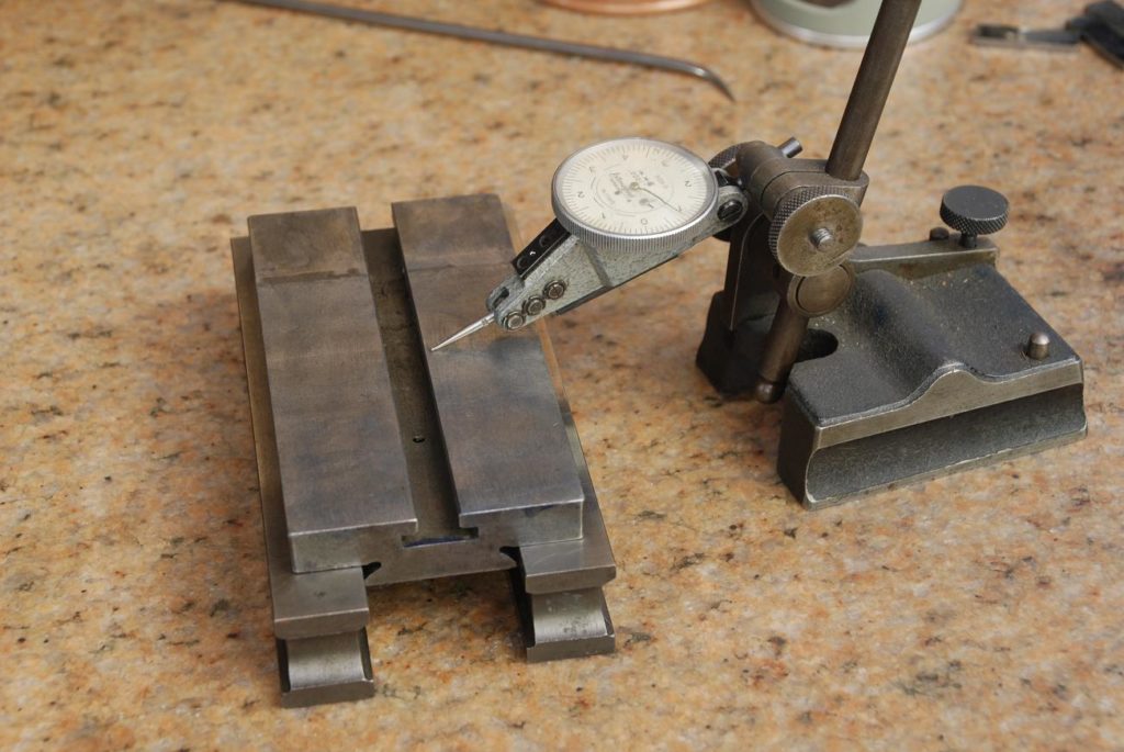
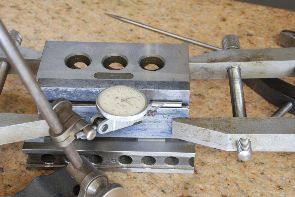
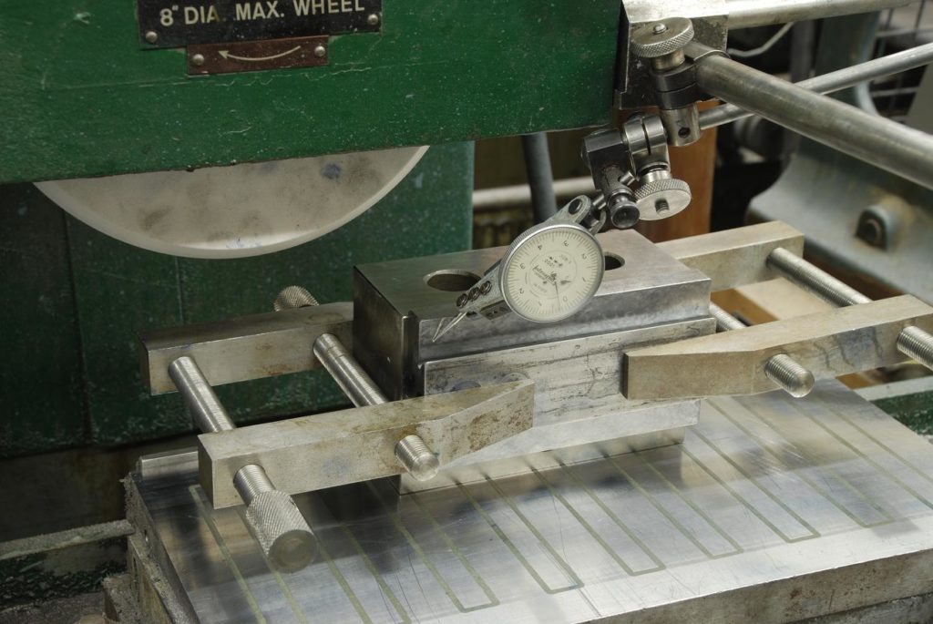
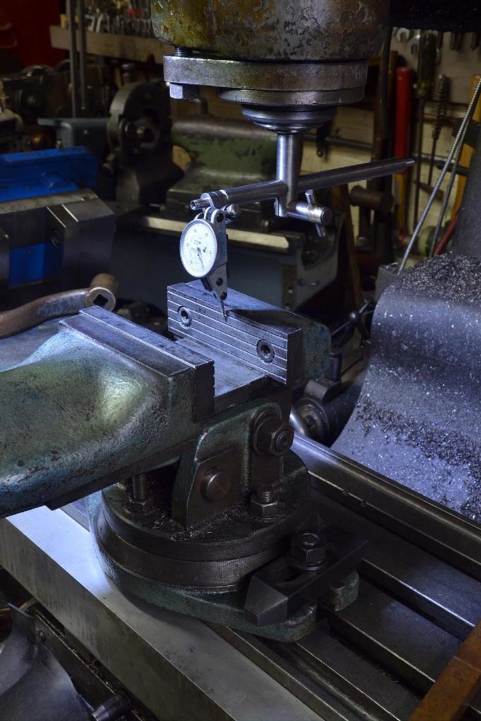
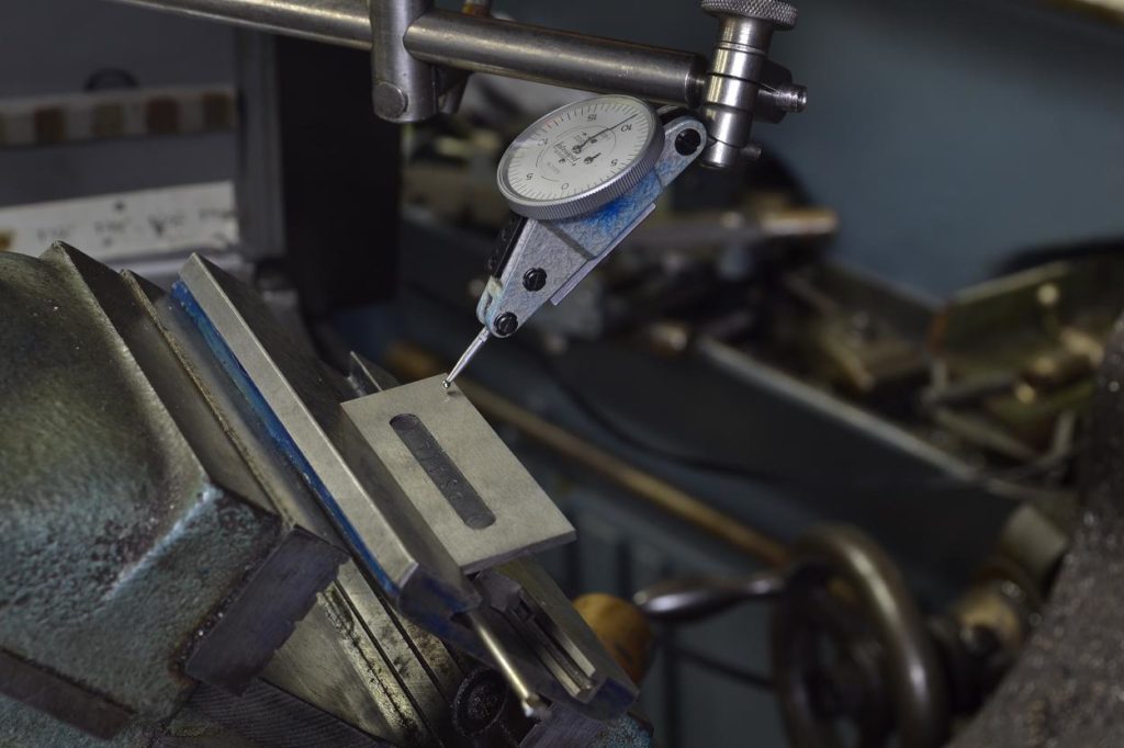
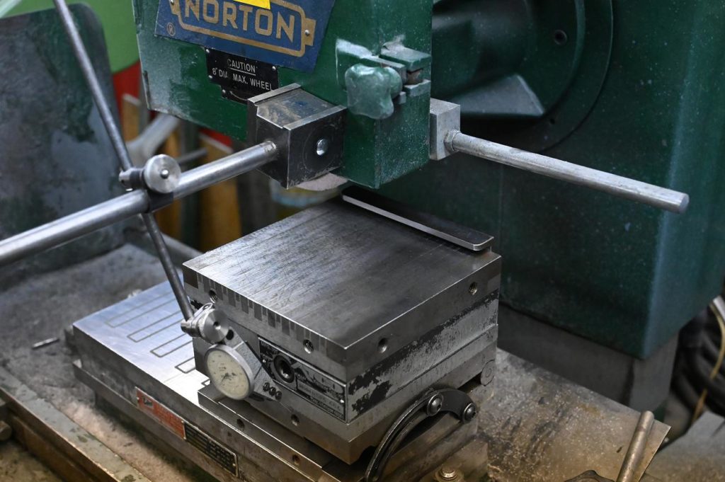
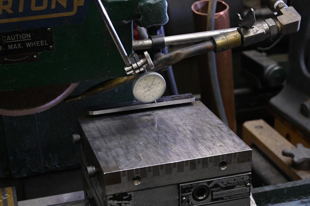
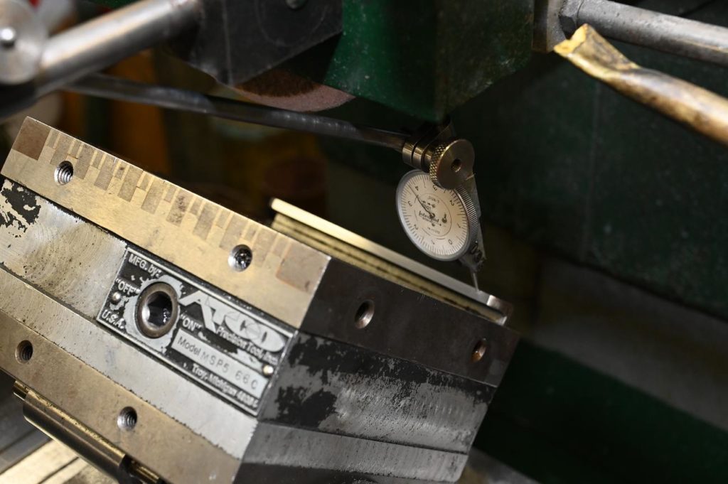
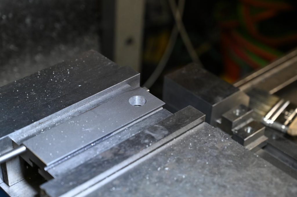
For each piece, we need the horizontal surfaces on the top and bottom parallel.
This is easily checked with a tenths indicator and a surface plate. If you were to scrape this, you would scraper flatness while constantly checking using the setup shown in the photo for parallelism
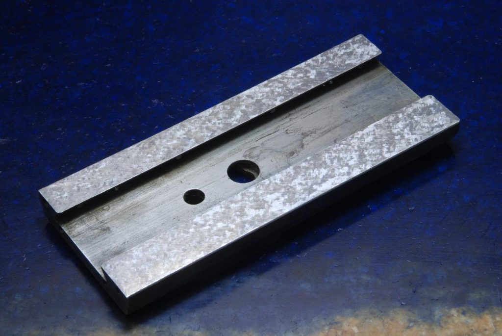
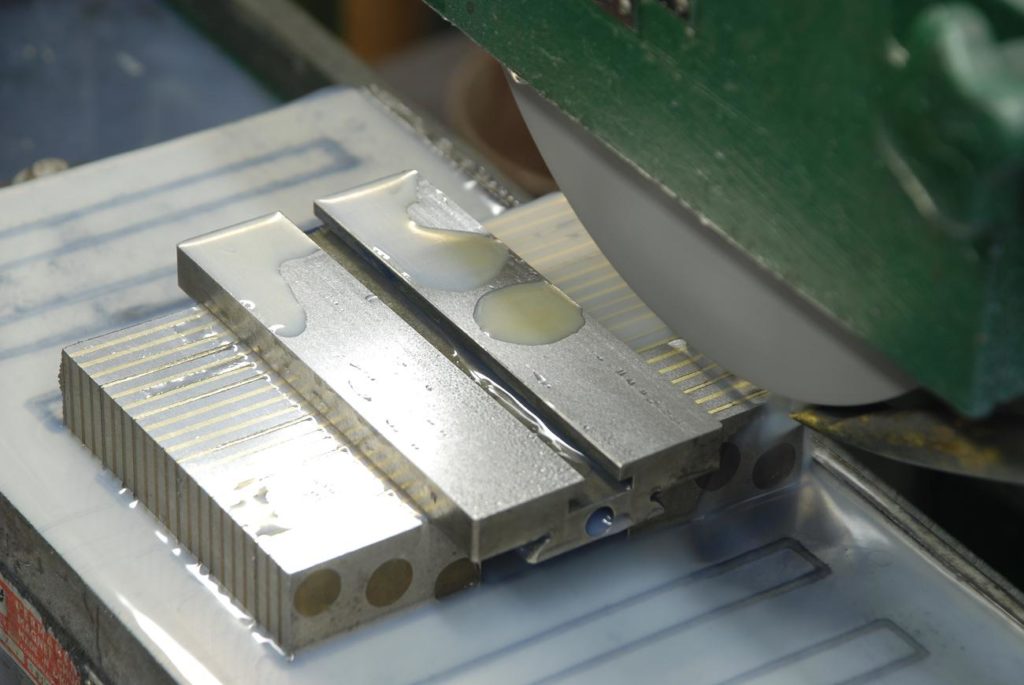
They finished ground surface
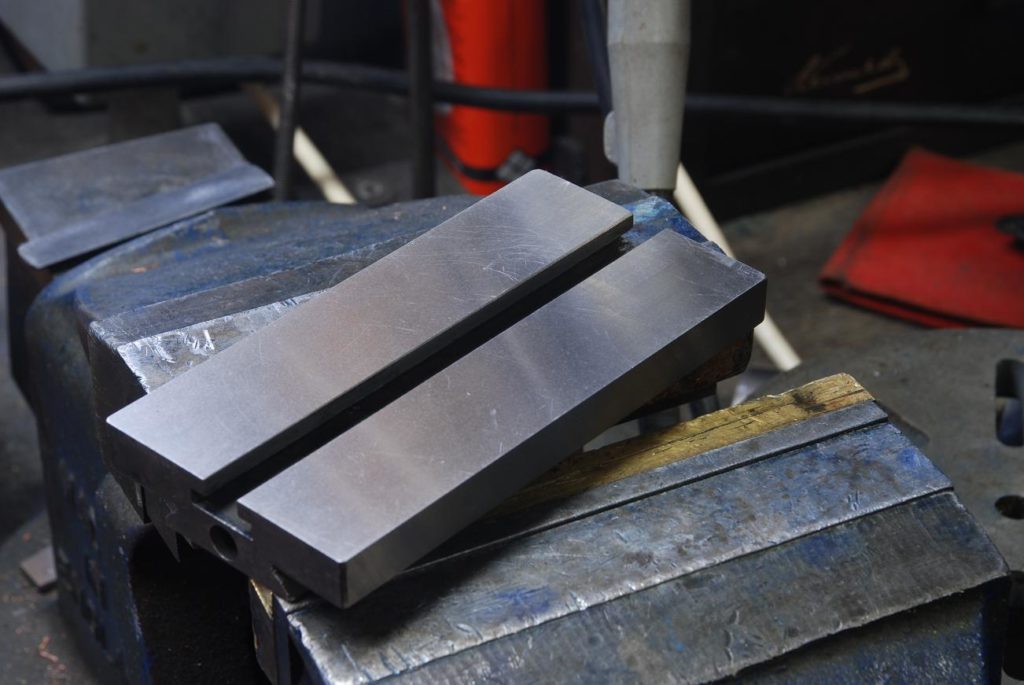
Nice to see some shiny and finished bits of work
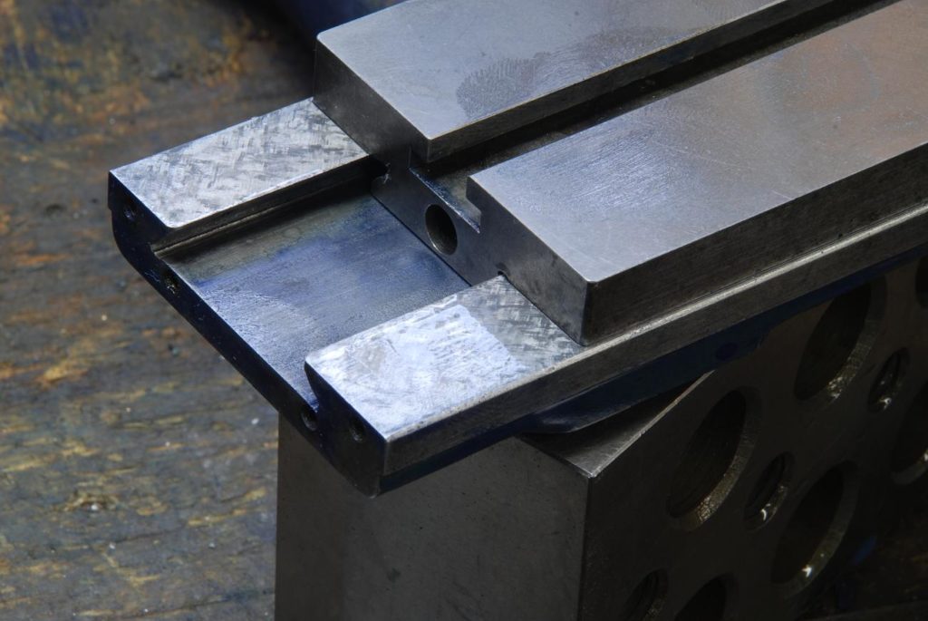
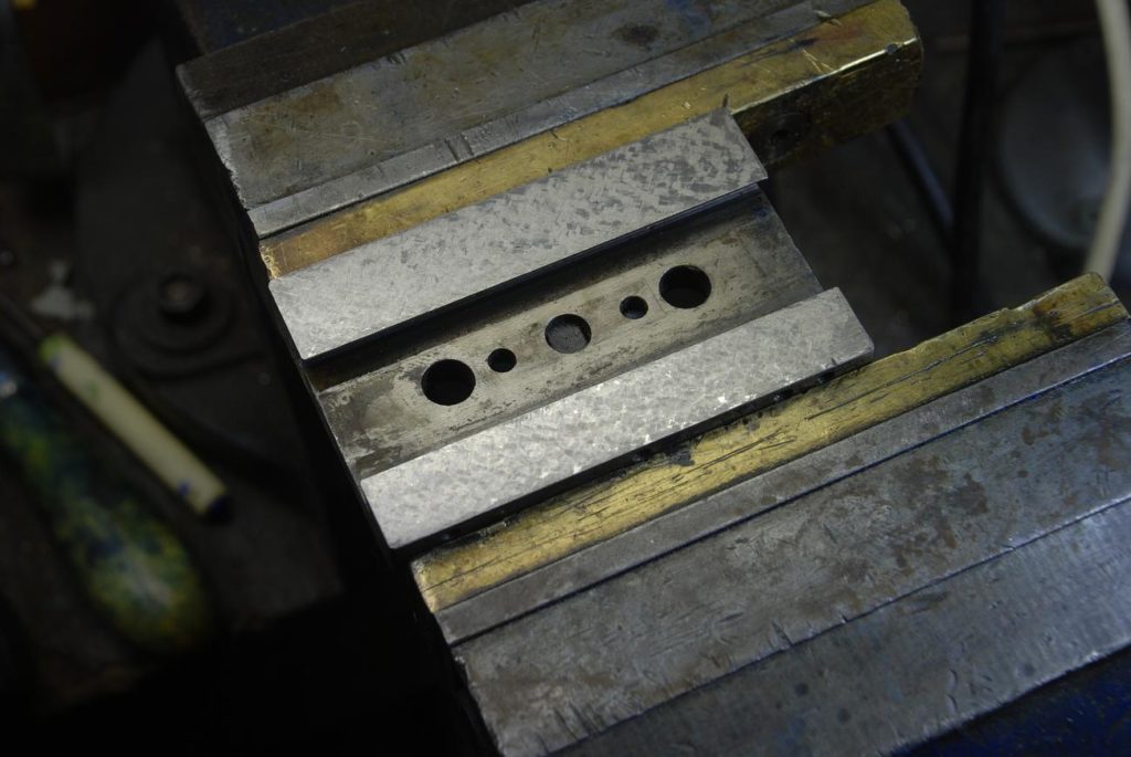
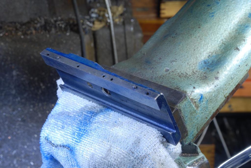
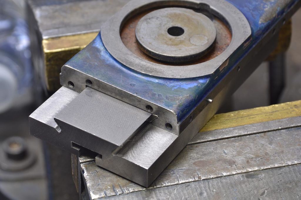
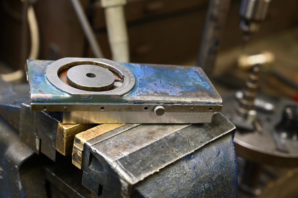
This photo shows all of the horizontal services complete
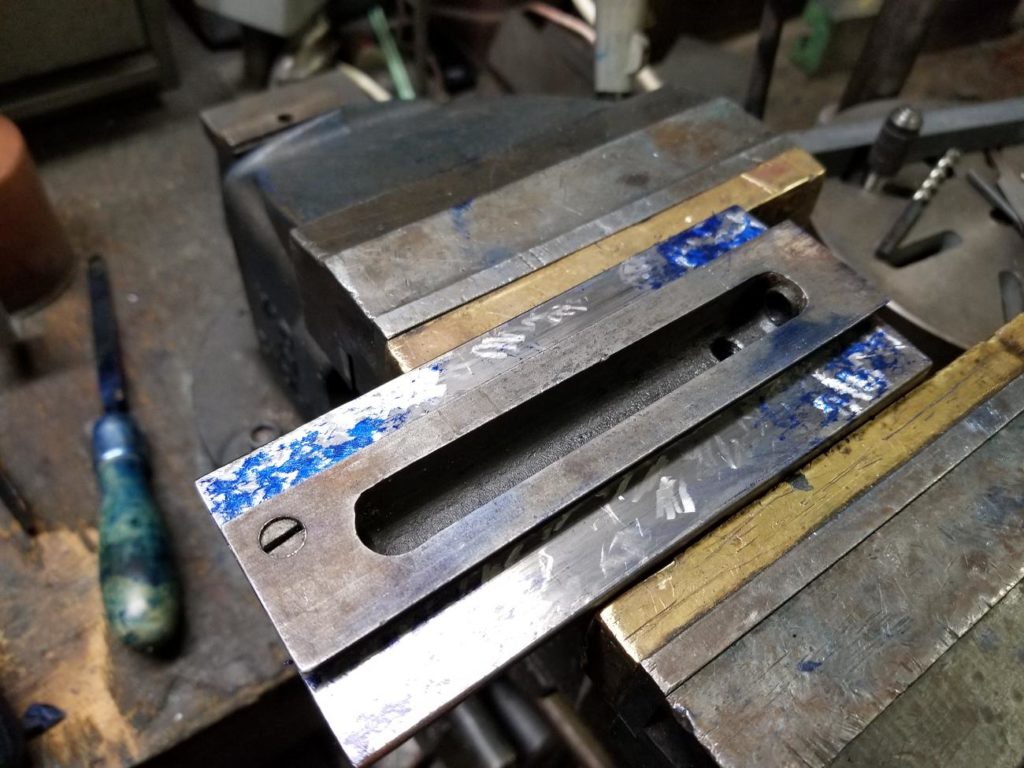
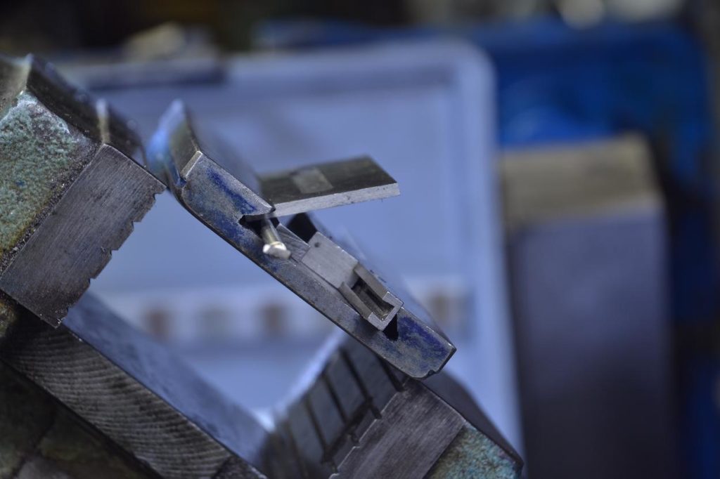
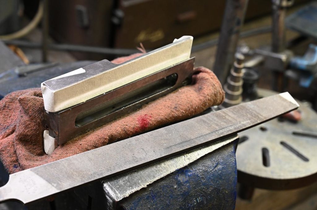
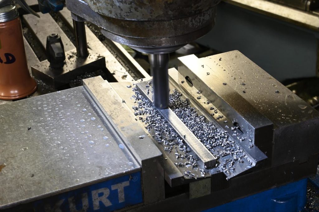
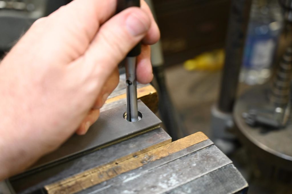
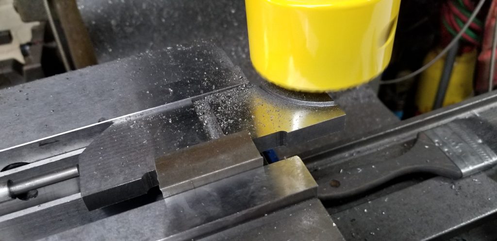
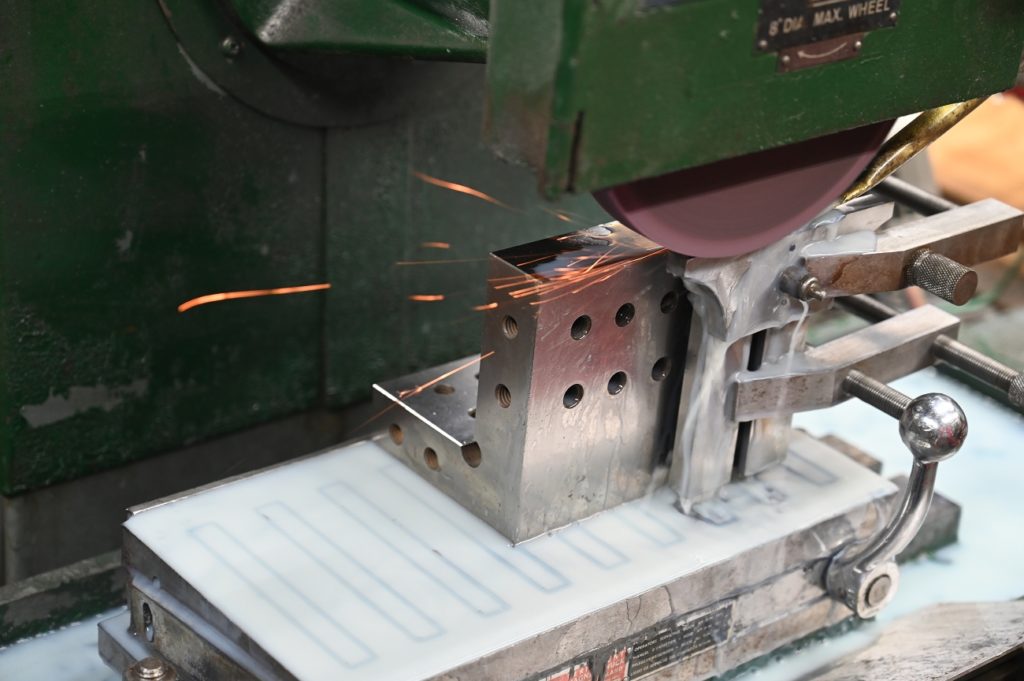
Frequently when doing dovetails a bit more clearance is needed in the corners to scrape the surfaces. These tap flute milling cutters are ideal. I want to keep material removal small and into the flat area not the angled area which is already very small
I decided to grind the male tapers. It’s somewhat less optimal than scraping however great results burrs till obtainable by running a hard Arkansas over the ground surface
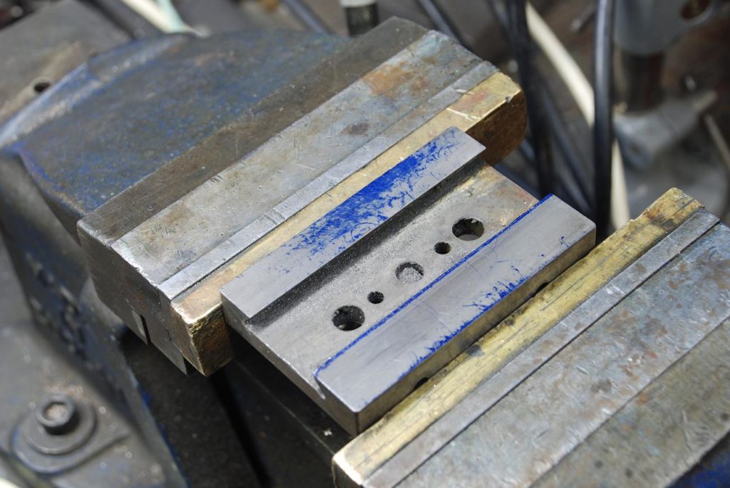
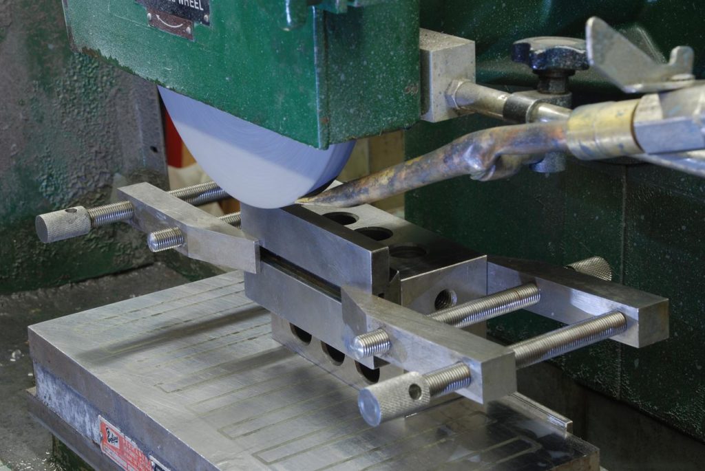
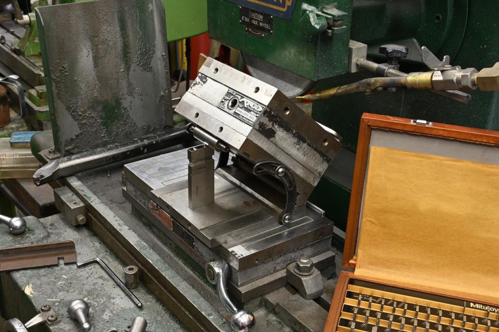
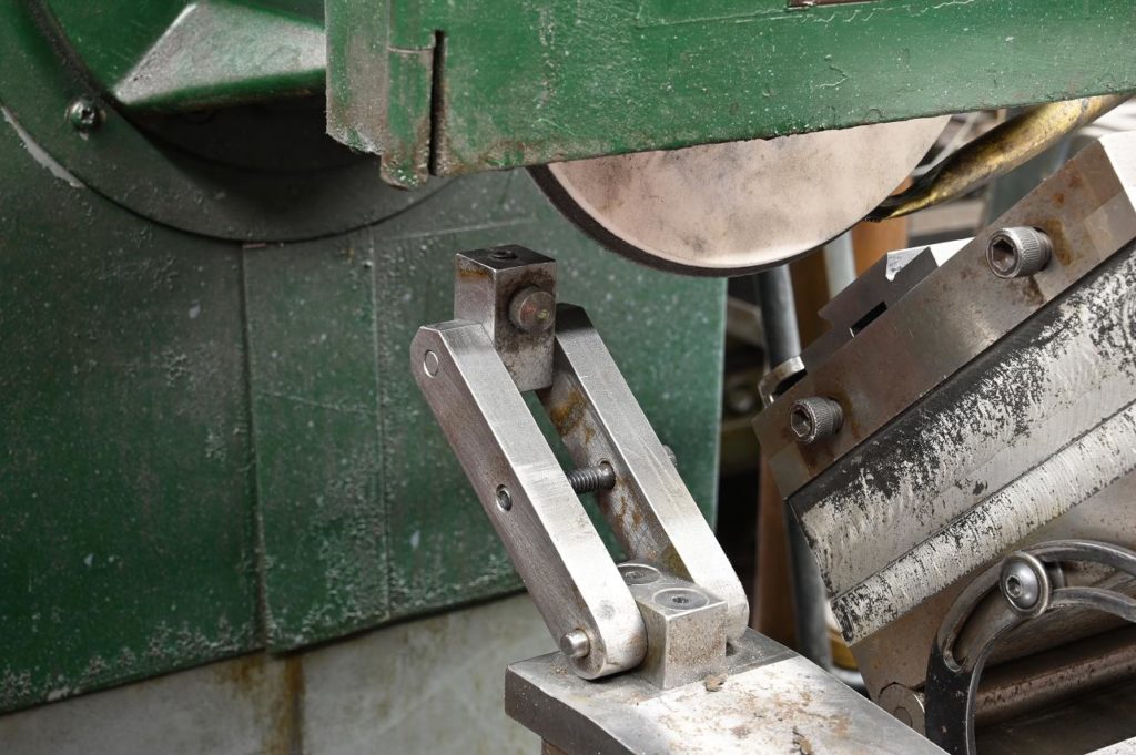
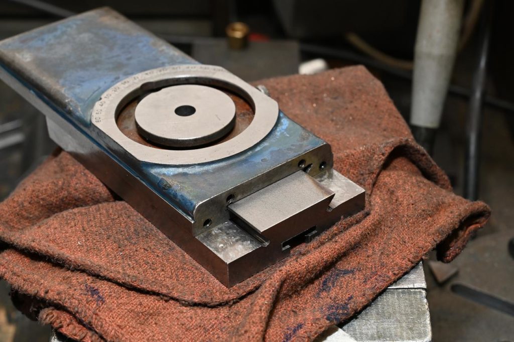
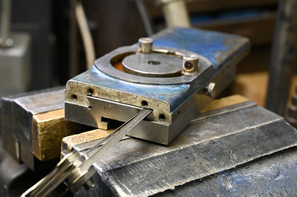
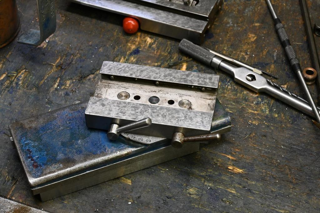
To either check or grind dovetails, a common setup is to use towel pins on the surface plate
With a parallel of known accuracy ( easily check with an indicator on the surface plate) set the work piece on the pens, on the parallel.
To check the Parallel is some of the dovetails, indicate as shown. To grind, use the same setup but clamp the work to an accurate toolmakers block
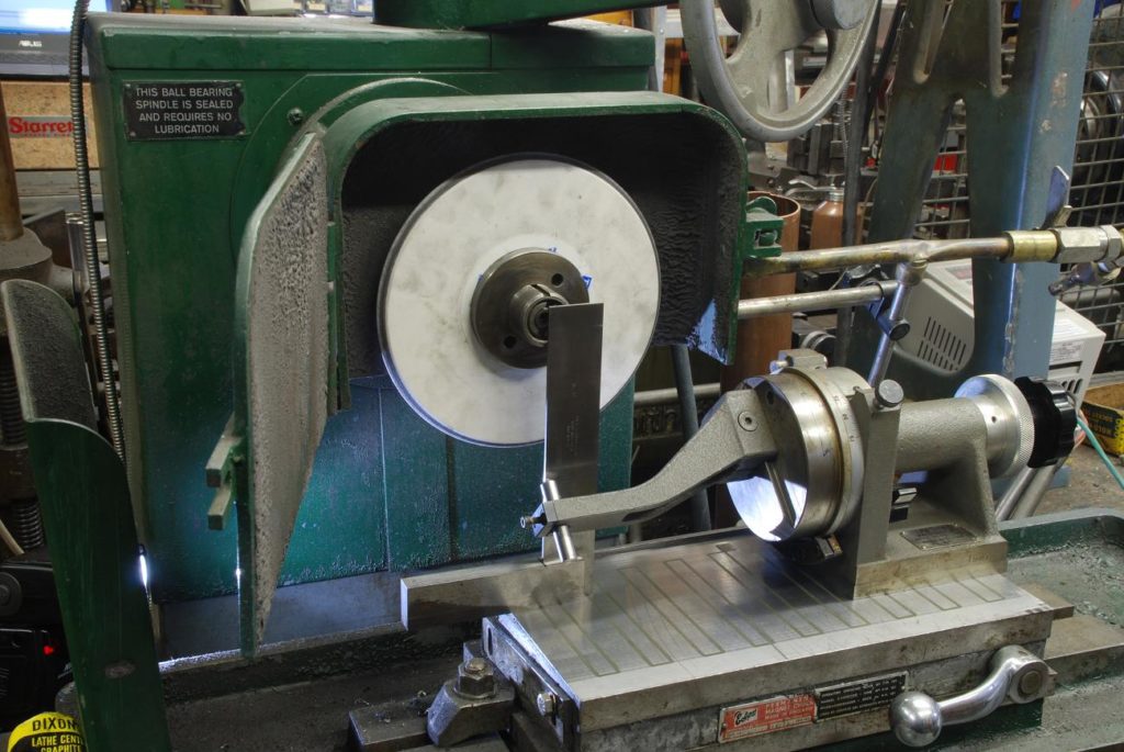
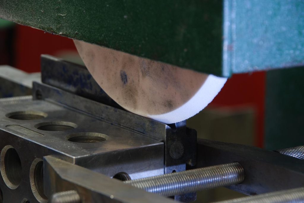
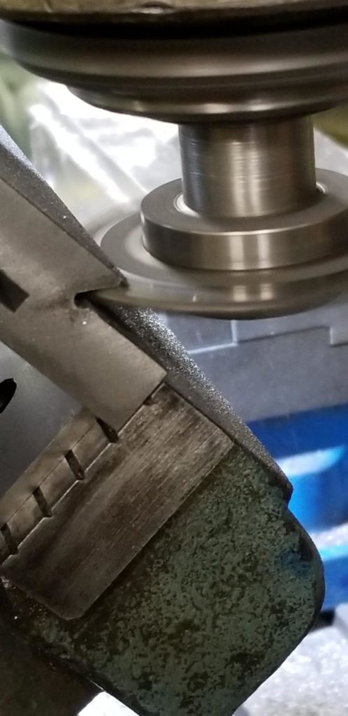
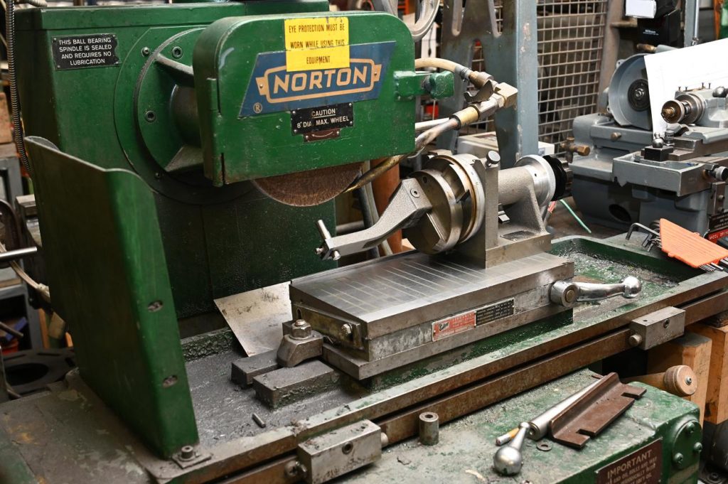
In this photo I’m setting up a radius gauge to dress the wheel to the correct angle
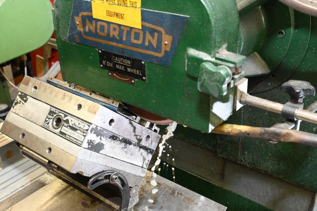
Grinding, contrary to popular belief, does not put very much of any grip around the shop. Most of what comes off the wheel is chips, and the extremely small amount of abrasive from the wheel where is for the most part captured in the flood coolant.
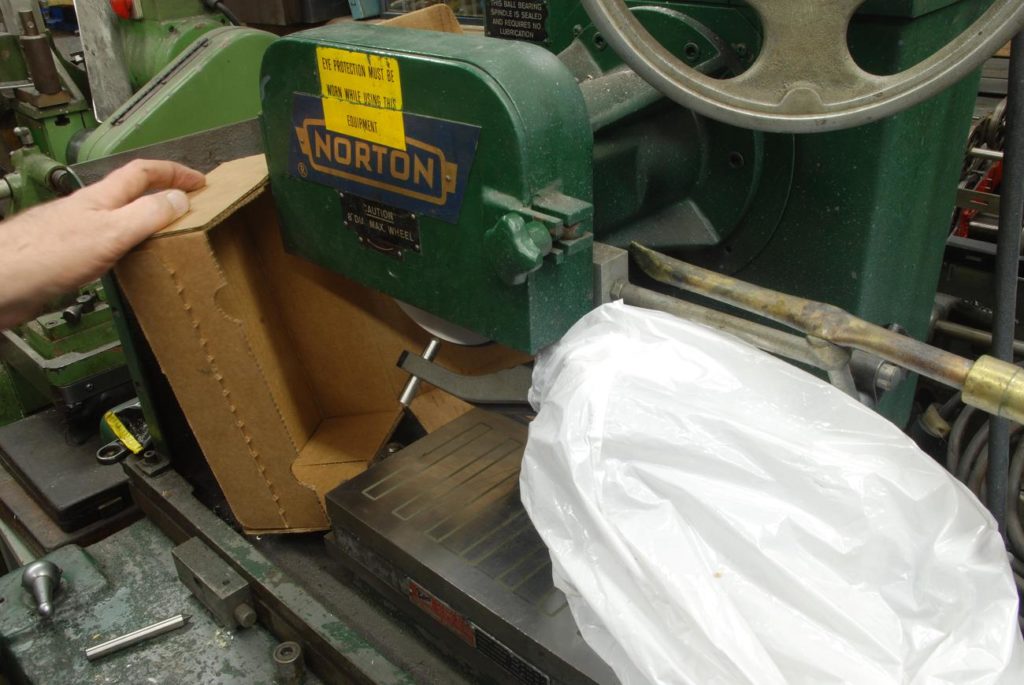
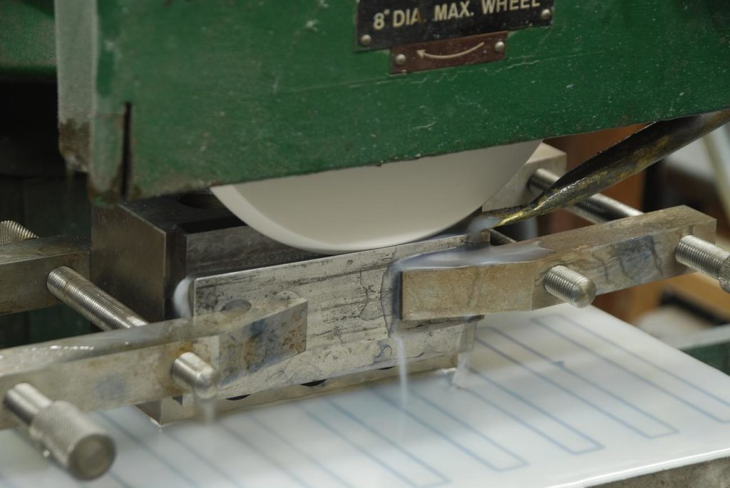
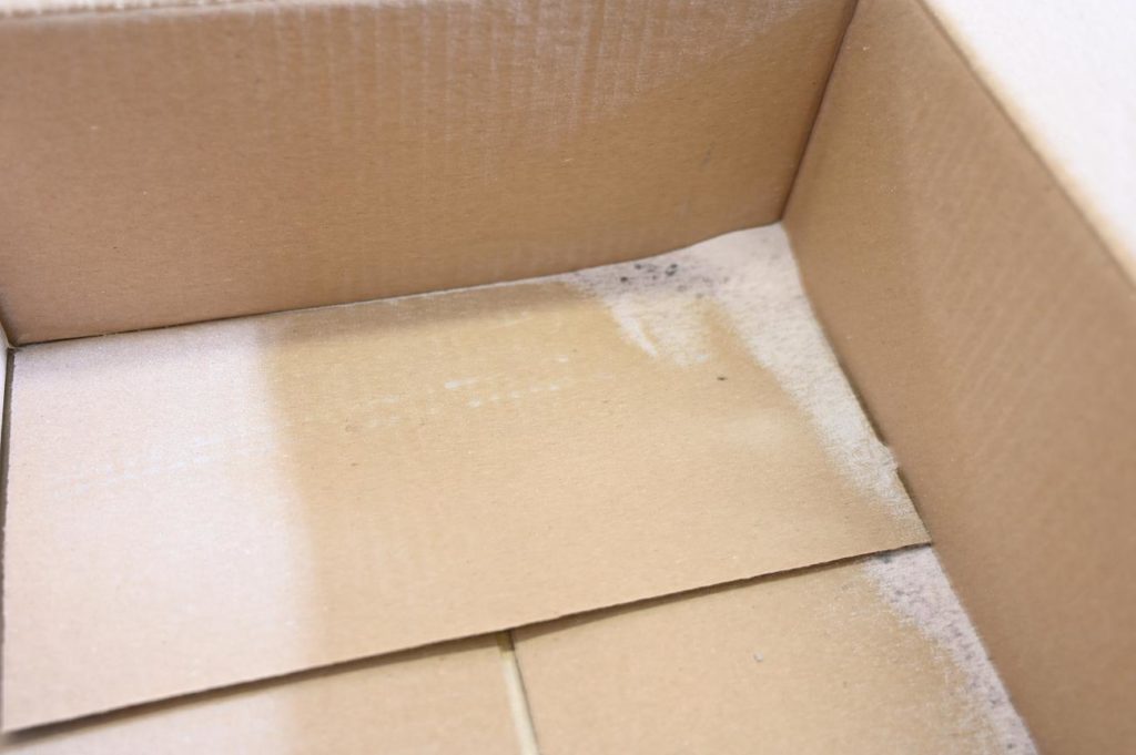
However with addressing does put perfect quantities of abrasive grit into the air. And this photo I’m detecting the precision angle dresser and trying to contain some of the grit with a cardboard box
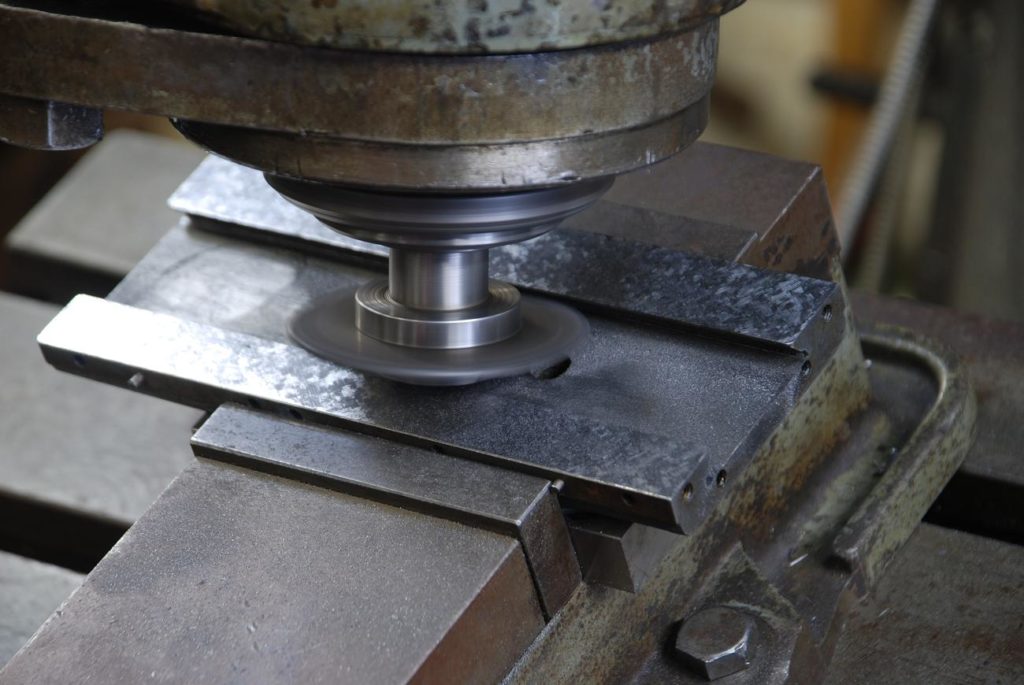
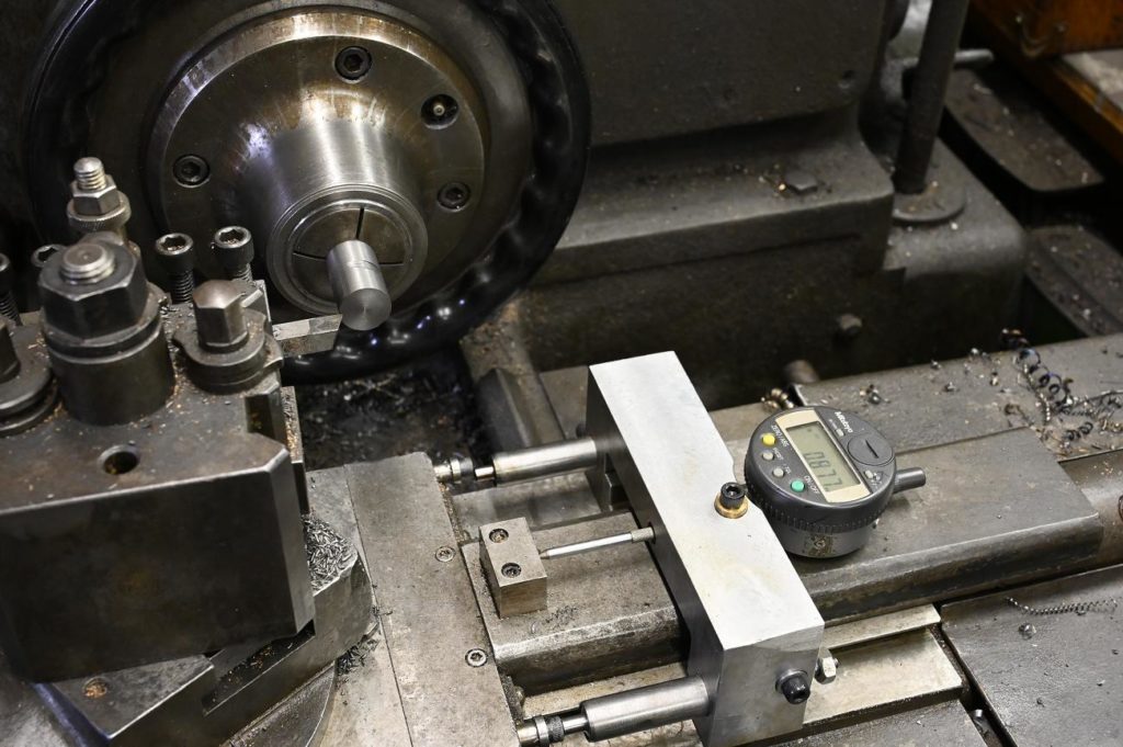
The work is carefully indicated in to the surface grinder accessed using a tenths indicator. It is imperative that this grind the exactly parallel to the horizontal surfaces
The wheel is ready for grinding
Really, in any kind of grinding, you need to traverse the wheel across the work so that the resultant surface is an averaging of different parts of the wheel contacting the work. In other words to grind a flat surface, you would move the work left to right and then move the work along the Z. axis Say 100 thou and repeat this across the flat surface. In grinding an angle like this we cannot do so so there is the risk that we will get a less-than-perfect surface with lines along the access of the grinder table. To mitigate this on using a very fine 150 grit wheel And Wellstone the surfaces within Arkansas stone after grinding
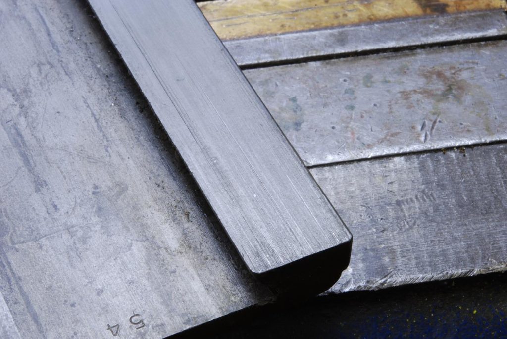
Using a setup similar to a shown above with dowel pins and the surface plate, I clamped parts toolmakers block and ground the outside edges. This creates a surface that we can rely on which is parallel to the dovetails
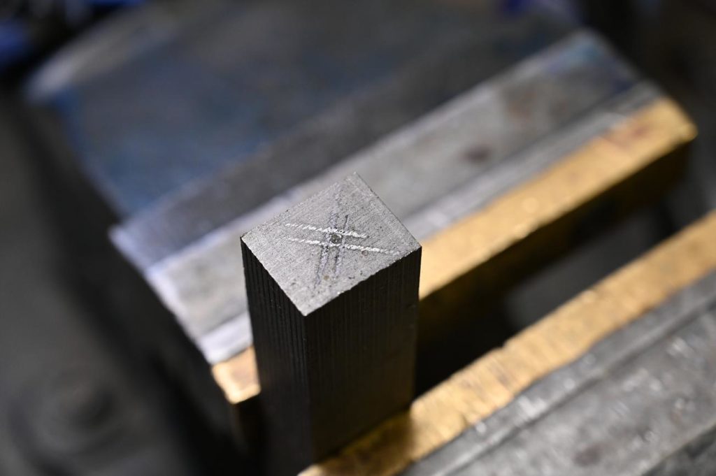
To get at the internal female dovetails, I had to make a reference. note that these references are made slightly acute of the dovetail their measuring And only one surface may be finished. ( although as a reference, it needs a very high quality finish)
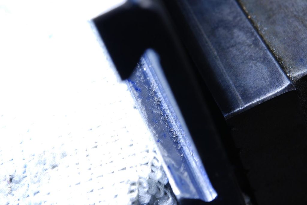
I’ve concluded that my grinding approach is a failure and I need a better way. I’ve found scraping the angle angled dovetail surface is all but impossible. Its just so small and an area and so difficult to see, heck its about impossible to even get a decent photo
Furthermore, I was unhappy with the fit of the bottom piece – that male dovetail on the X axis feed.
As I want this project to come to factory new standards and performance, I decide to remake this piece. Feels like being in marathon and finding out the distance has been increased
A suitable disk of durabar was under the bench, again, thank goodness for the bandsaw
I lightly flycut one side in the vertical mill then did the dimensions work in the horizontal mill
I lightly flycut one side in the vertical mill then did the dimensions work in the horizontal mill
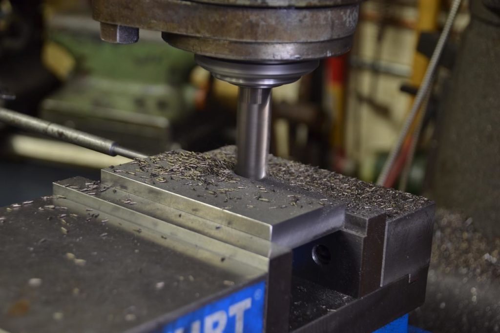
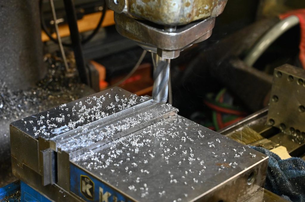
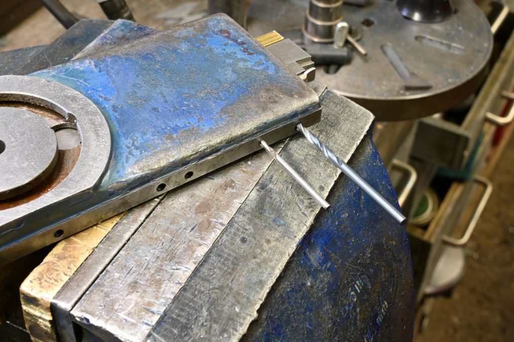
Back to the horizontal mill to mill the slot – slots turn out perfect on the horizontal mill and can usually be done in one pass….vs the misery of end milling them
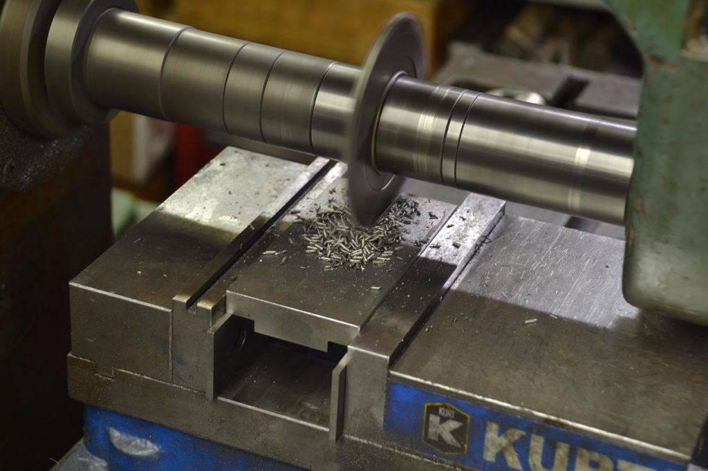
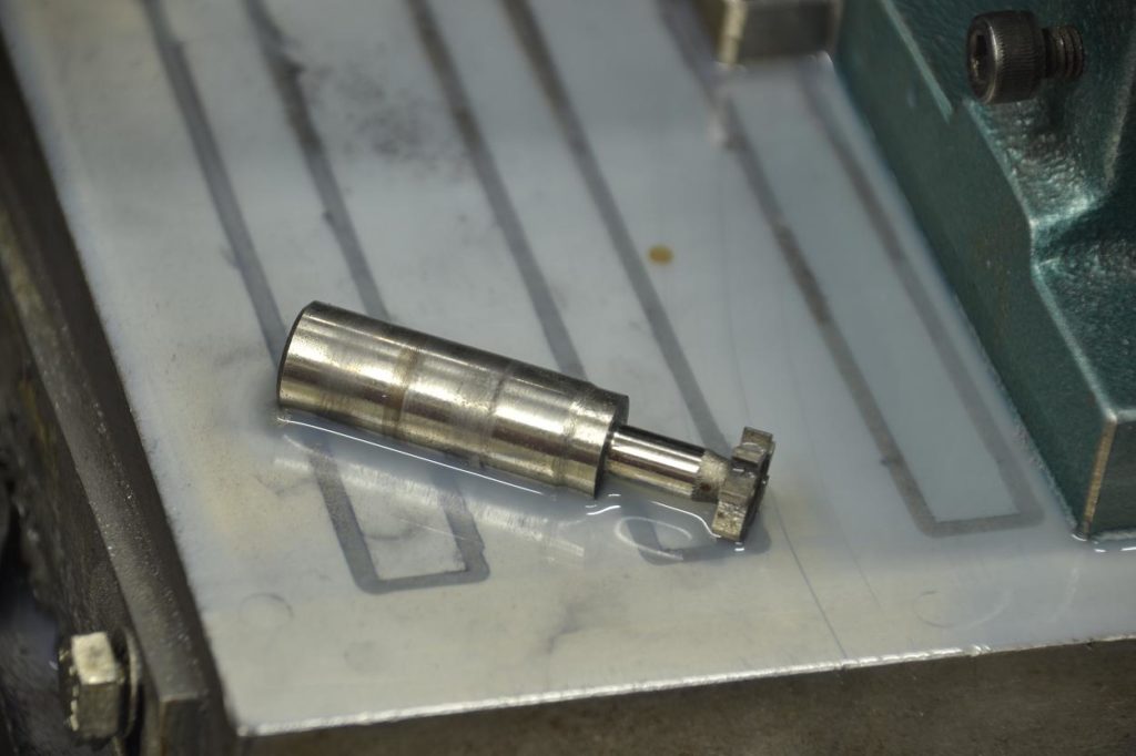
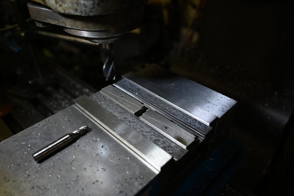
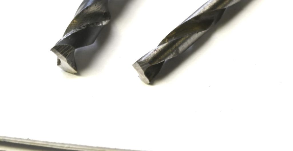
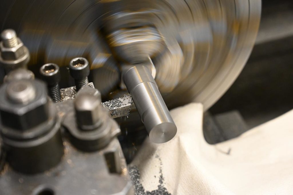
To get the bottom of the dovetail, I had to grind down the shaft of a cutter
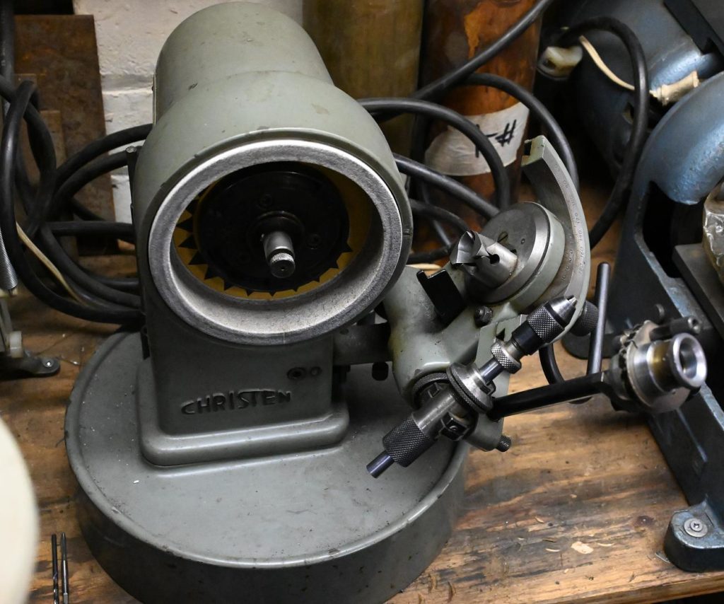
While having all the tools makes jobs go more quickly, there is almost always an alternative that lets you get things done with less. Before getting a grinder (and a centreless pin grinding attachment) this cutter would have been home made to the dimensions required
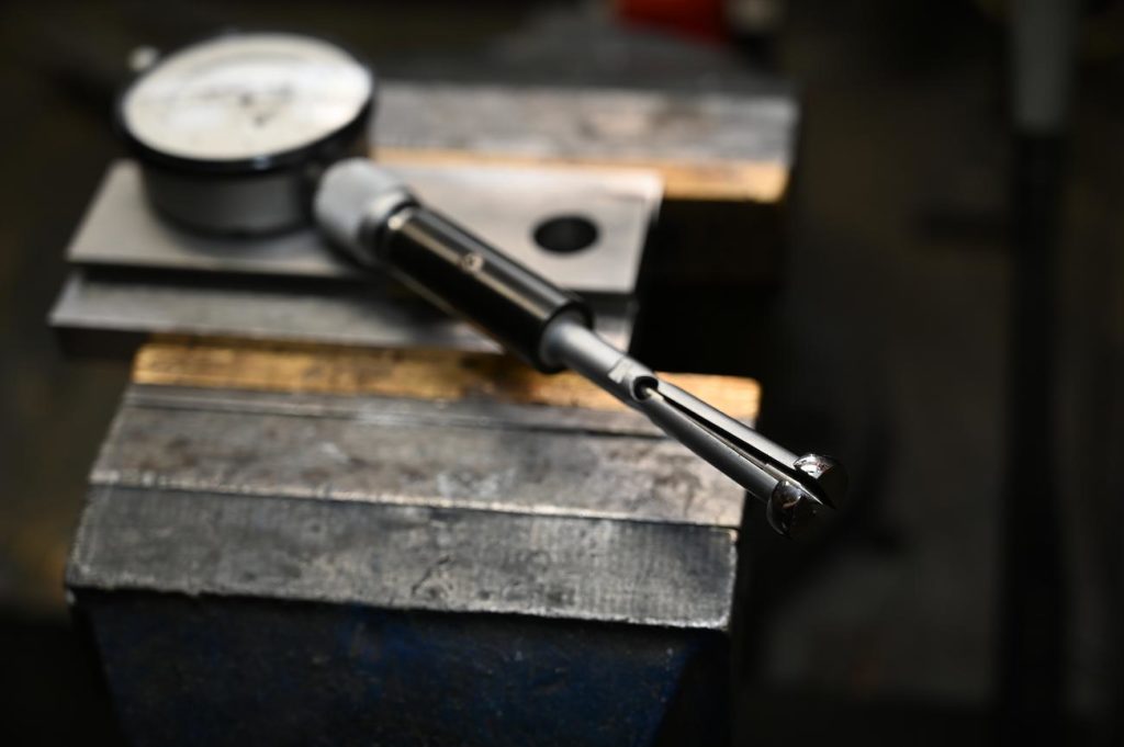
The cutter ready to go
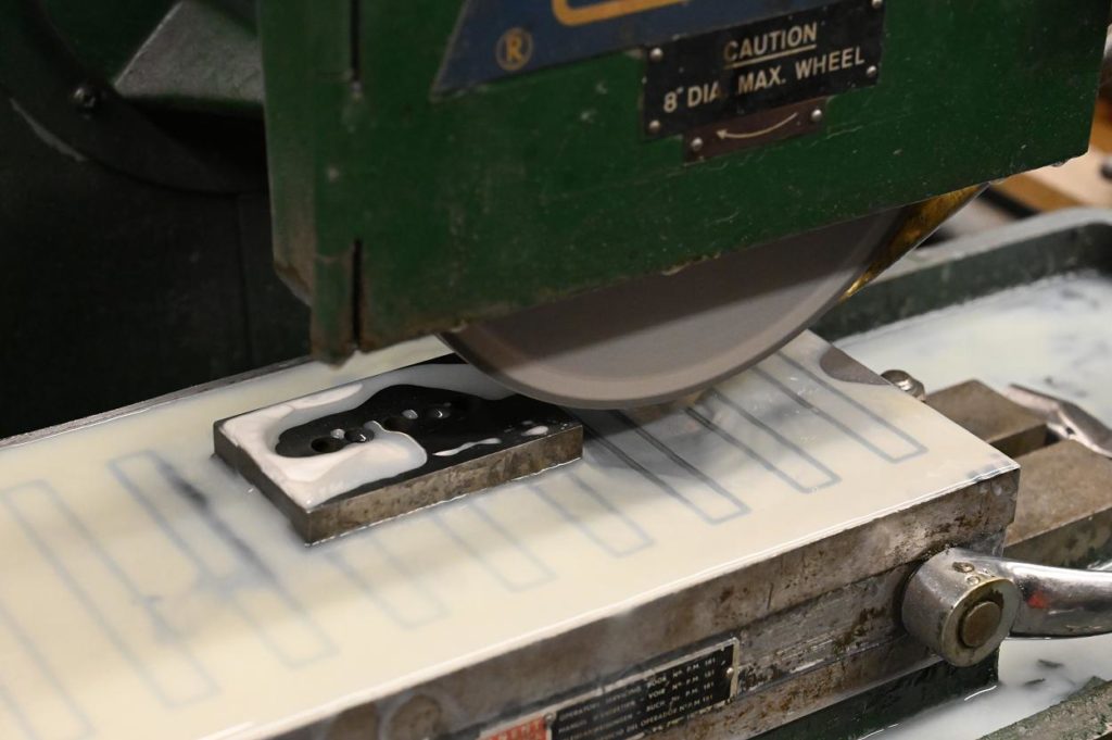
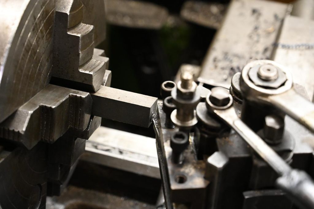
The dovetails were some odd angle, close to 18 degrees. I roughed them out with a 45 degree cutter
The dovetails were some odd angle, close to 18 degrees. I roughed them out with a 45 degree cutter
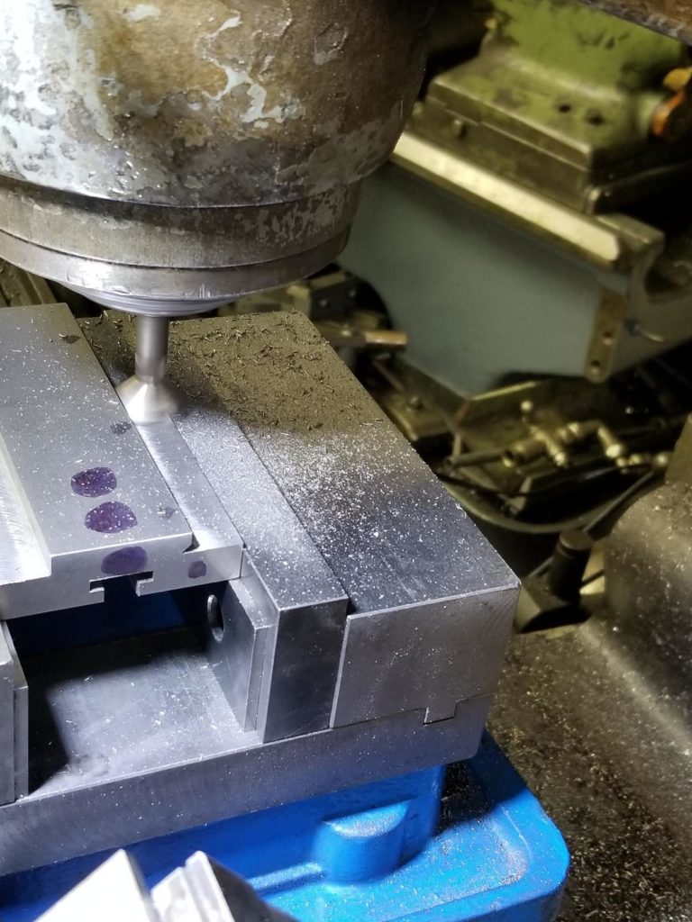
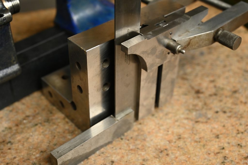
To finish mill the dovetail angles, given their oddball angle, I dialed in a tilting vise
Then I jammed a think parallel against the angle dovetail surface of the mating part. An adjustable parallel is used to do the jamming
By indicating across the top the parallel, should have the angle very close
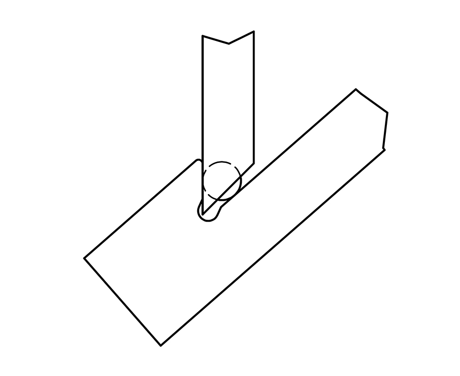
Then its a matter of using a tap flute cutter (rounded) to finish mill the dovetail, and the clearance slot. By doing it this way I get the clearance necessary for scraping, with compromising the surface area of the dovetail angled face
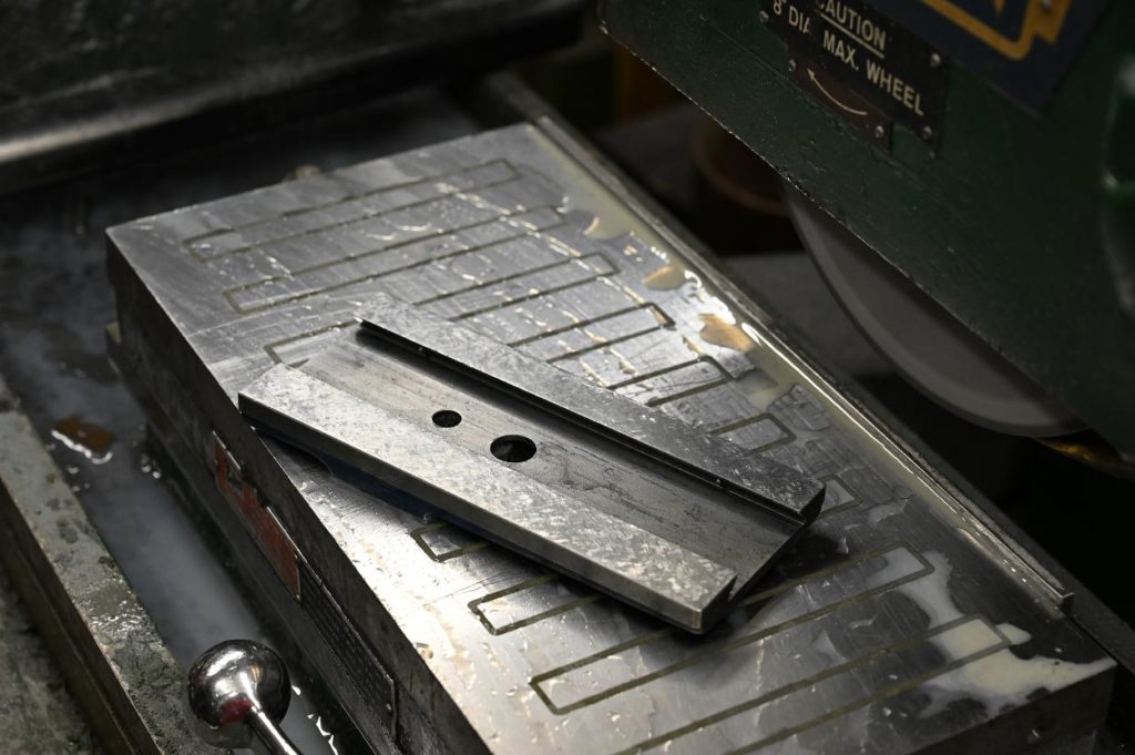
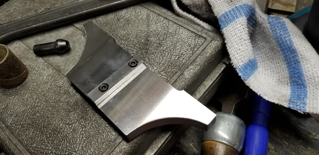
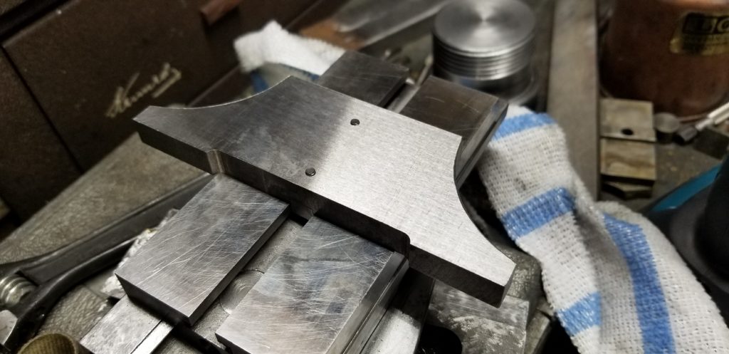
The replacement piece fits well
Now its time to scrape the horizontal surfaces. Fortunately this is a really small area, and with the matting part to print, it was completed in a few hours
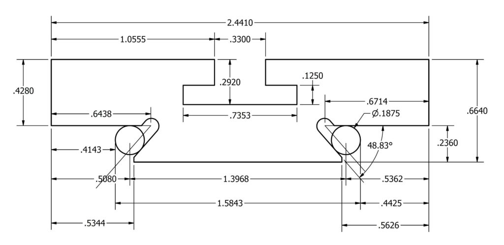
The new piece I made, as shown in the drawing (a sketch really, just for my own use) ends up with the full aera of the angled dovertail surfaces and the relief groove
The new piece I made, as shown in the drawing (a sketch really, just for my own use) ends up with the full area of the angled dovetail surfaces and the relief groove
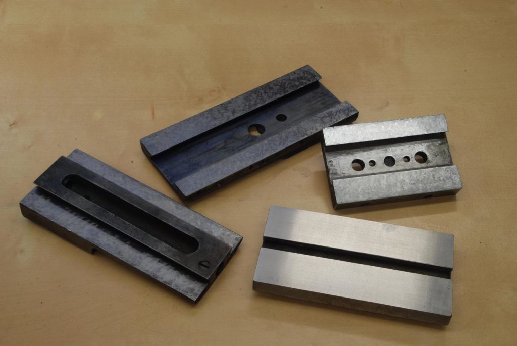
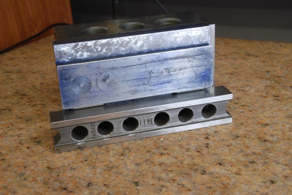
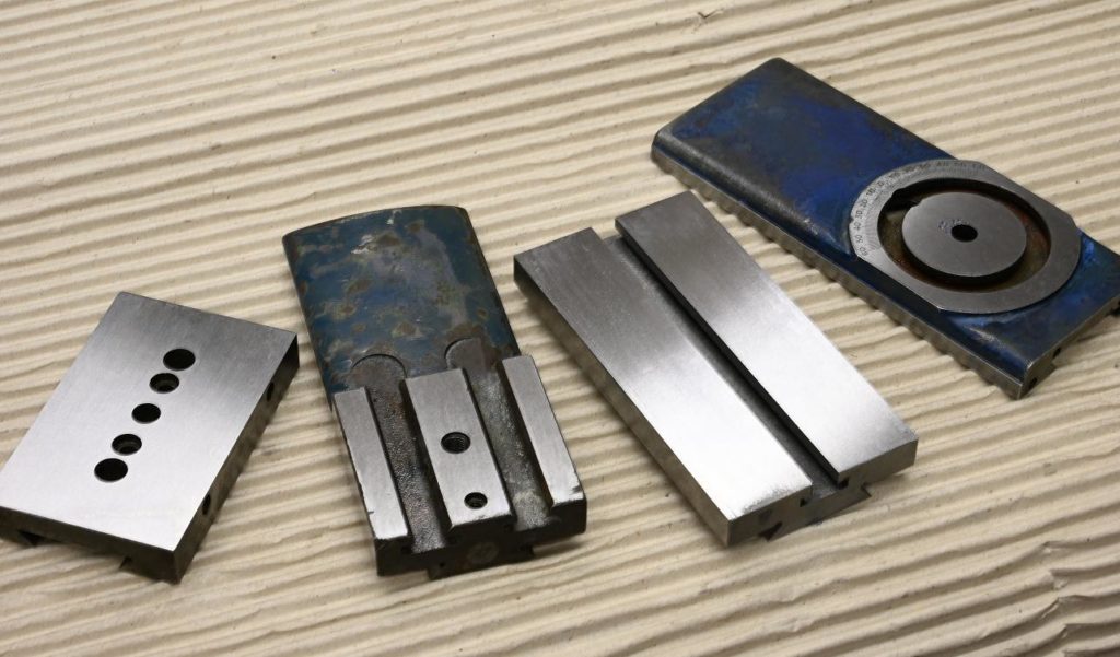
There are four pieces that make up the slide rest “pancake stack”. On each I’ve got perfect flatness on one side, achieved through scraping.
Note how even with a grinder, scraping is the preferred way to create this flatness. Its more accurate even use the right techniques, grinding imposes some clamping forces.
Once we have one surface flat via scraping, grinding the other is easy as the part wont be distorted (given a flat is contact with the mag chuck)
In any event, to try my plan for grinding the angled dovetails, I need the side opposite each scraped side parallel to it as this surface will become a reference.
The two female parts are easiest and done first
Here is the scraped surface, it will go against the chuck. Of course all grinding is done with flood coolant
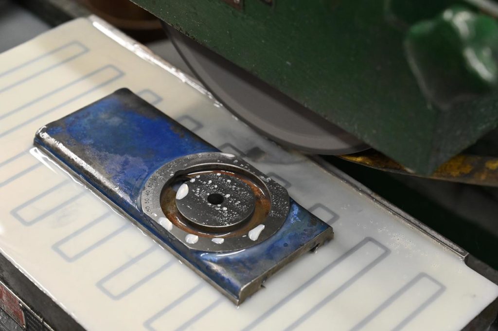
I took just the slightest skim so as to not degrade the degree markings.
Grinding is done with a 60 grit J hardness wheel and sparked out….shooting for the eyeball freezing finish
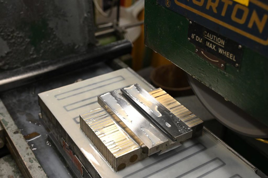
the mating male parts are put on mag chuck parallels
Next up is grinding the angles. My plan is to grind both mating parts with one sine chuck setting so I get a perfect mate
While grinding on the OD of the wheel was a failure, I think I will be able to do so using the side of the wheel as shown in the sketch.
Every beginner has it drilled into them never grind on the side of the wheel, and it is good beginner advice – tried, true and safe. However any tool maker knows you do grind on the side of the wheel, when absolutely necessary and very carefully
Putting that sketch into practice will be the next adventure
The angle/radius dresser is set up. This angle is clearance so all that is needed is something more acute than the dovetail angle
The angle dresser is covered with a plastic bag (its a precision thing deserving protection) and a cardboard box placed placed behind the wheel to catch most of the grit
A mag sine chuck is set up. First, I carefully indicate the body of the chuck parallel to the grinder’s table motion
Then I just kiss the stop with the side of the wheel and double check it against the tables motion
Using a gauge block stage the angle is set. In one sense wouldn’t matter if the angle was exactly the same as that from the factory, however by setting the same I’ll not worry about grinding the top non bearing surfaces supporting the gibs
the back side of the wheel is dressed and I leave the dresser in position so I can freshen up the wheel during the job
It is critical that the back side of the wheel is relieved, done by hand with a norbide stick
Just before grinding one final check is done with an indicator. This is really an integrity check of the the sine plate
Happily grinding away. Because the sideways force on the wheel changes between the ends and the middle (where all of the wheel is in contact with the work), a very long spark out time is required
Of course you can;t see the relief in the side of the wheel, but this shot gives a good sense of the work set up
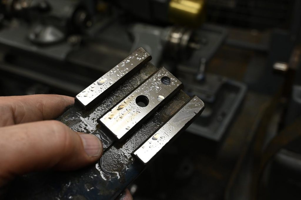
With some tape protecting the scraped surface, burrs are removed and the edge rounded over
Finished mating parts.
The angles on all four parts are done at the same set up, so get perfect alignment of the angles.
Also, as all sides were ground parallel, the dovetails are now parallel to the sides as well
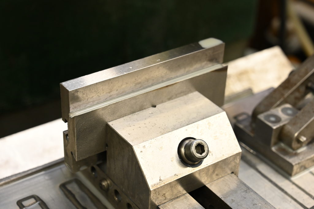
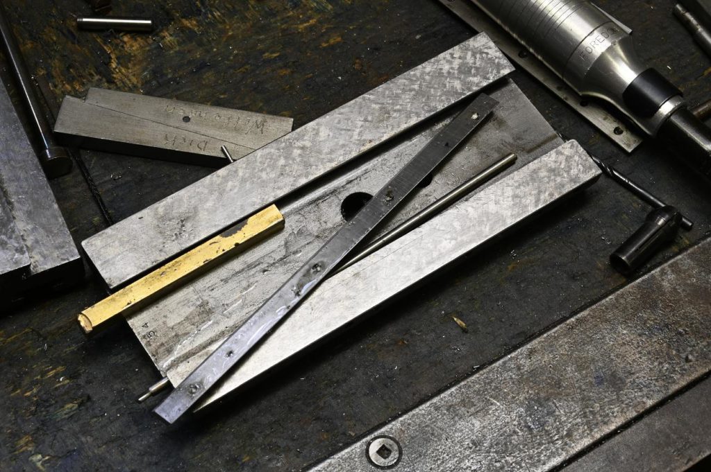
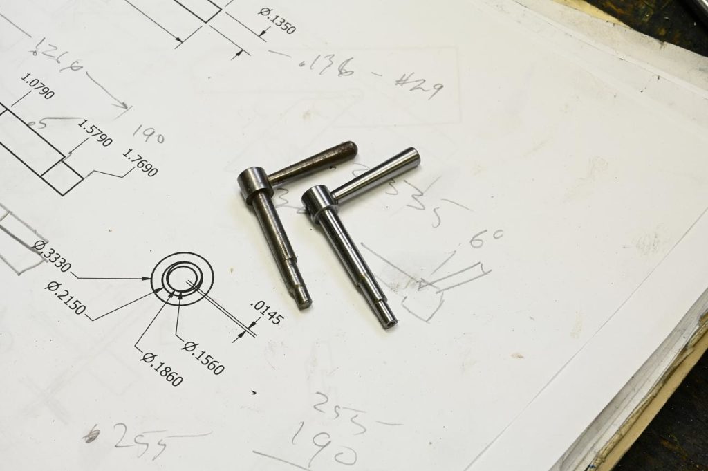
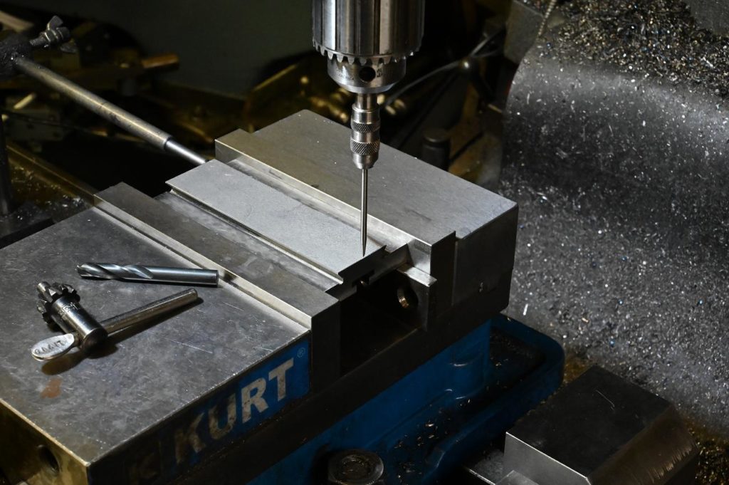
I need to make a gib for the bottom assembly. Small tapered end feeler gauges are ideal for measuring the width of the required gib
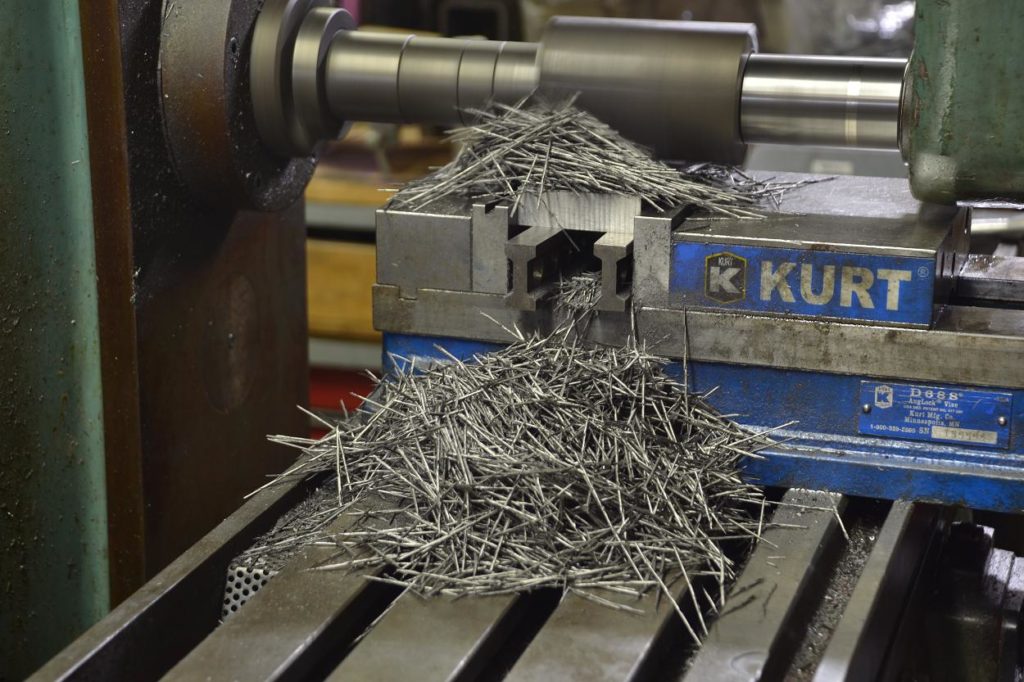
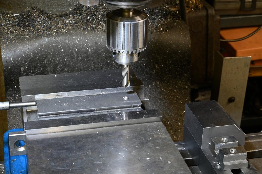
A piece of steel is being milled away. Taking many cuts, flipping the work in between, to machine out the banana shaped distortiuon you get from the bar stock’s rolling stresses
Don’t forget that prior to Kurt vises, men used hold downs to stop material lifting. Even with a Kurt, I regularly use them especially for small pieces. While they re less convenient, they do work better than an angle lock vise at firmly holding work down. They are by far the best way to hold thin material
Next, its onto the grinder. With a 60 grit wheel, get the best finish you can
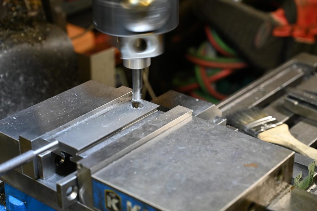
You can tilt the head to mill the angle on the gib, but its often faster to use the part it seats on as a fixture. Just jam it in place.
With large work pieces I’ve use machinist jacks however in the this case (everything is smaller) I used adjustable parallels. I used a machinist parallel clamp on the ends of the adjustable parallels to put some compression on the gib and clamp it in place
Lorem ipsum dolor sit amet, consectetur adipiscing elit. Ut elit tellus, luctus nec ullamcorper mattis, pulvinar dapibus leo.
Lorem ipsum dolor sit amet, consectetur adipiscing elit. Ut elit tellus, luctus nec ullamcorper mattis, pulvinar dapibus leo.
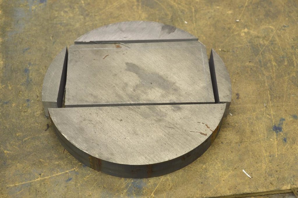
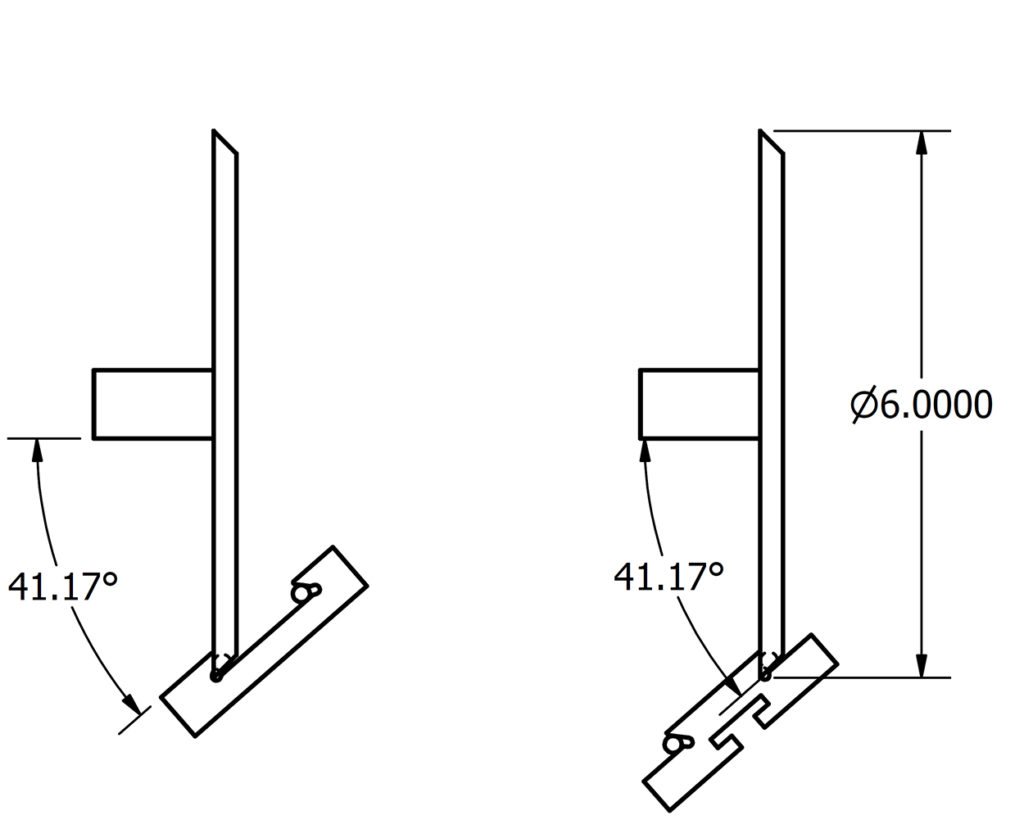
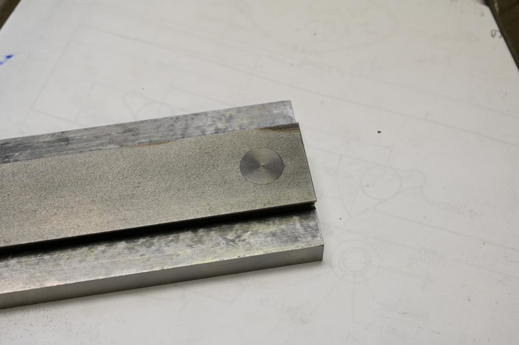
The slide rest square was missing on this lathe. Work started with a nice piece of Durabar
A hole saw made quick work of the profile. After the edges were filed and abraded smooth
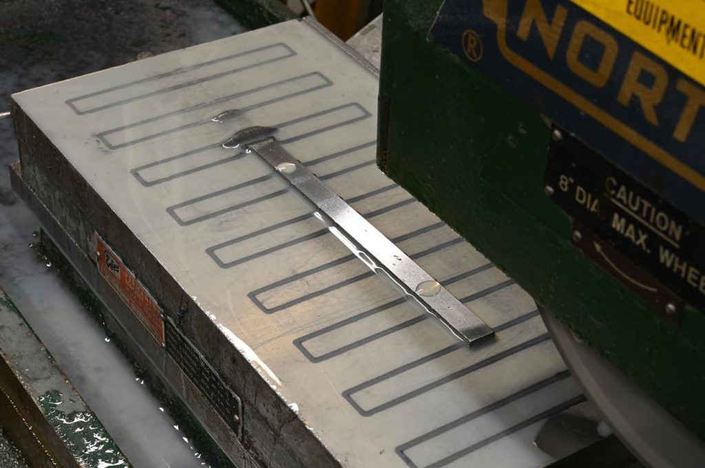
Then the part is ground to thickness. There is no great accuracy required for the thickness, however its visible so wanted a grround finish
A rectangular piece is ground to very carefully and exactly fit the slot in the bottom of the slide rest
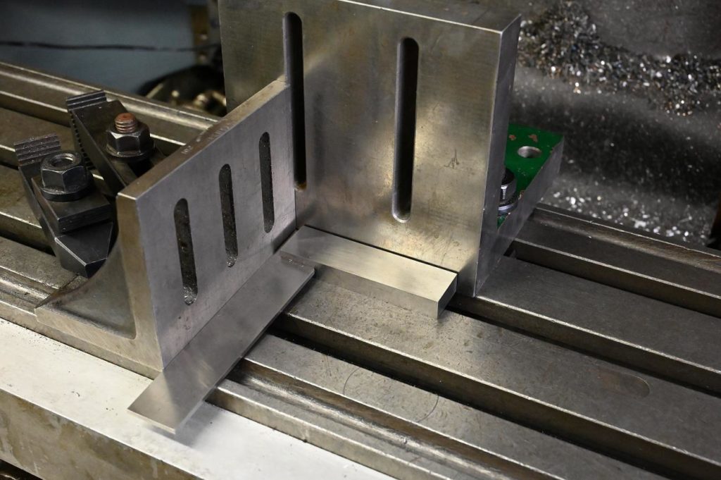
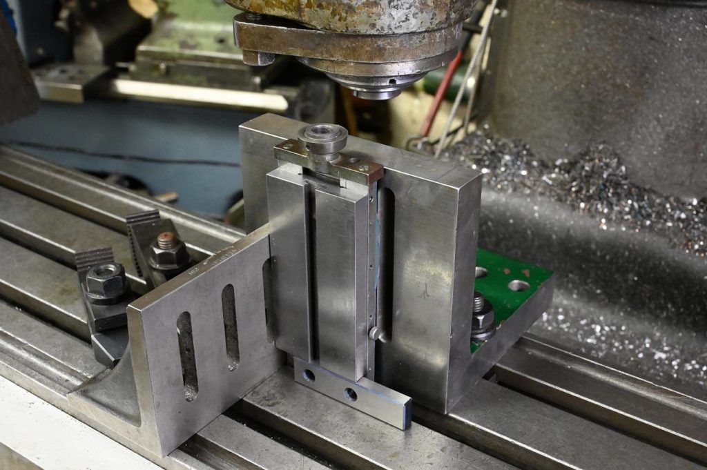
Next, the work is mounted on the slide rest. I used a square to make sure the sliderest was vertical then clamped the work piece/slide rest assembly to an accurate angle plate.
A quick run through the grinder and the square should be square!
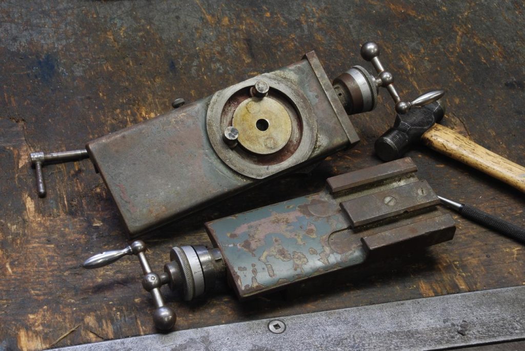
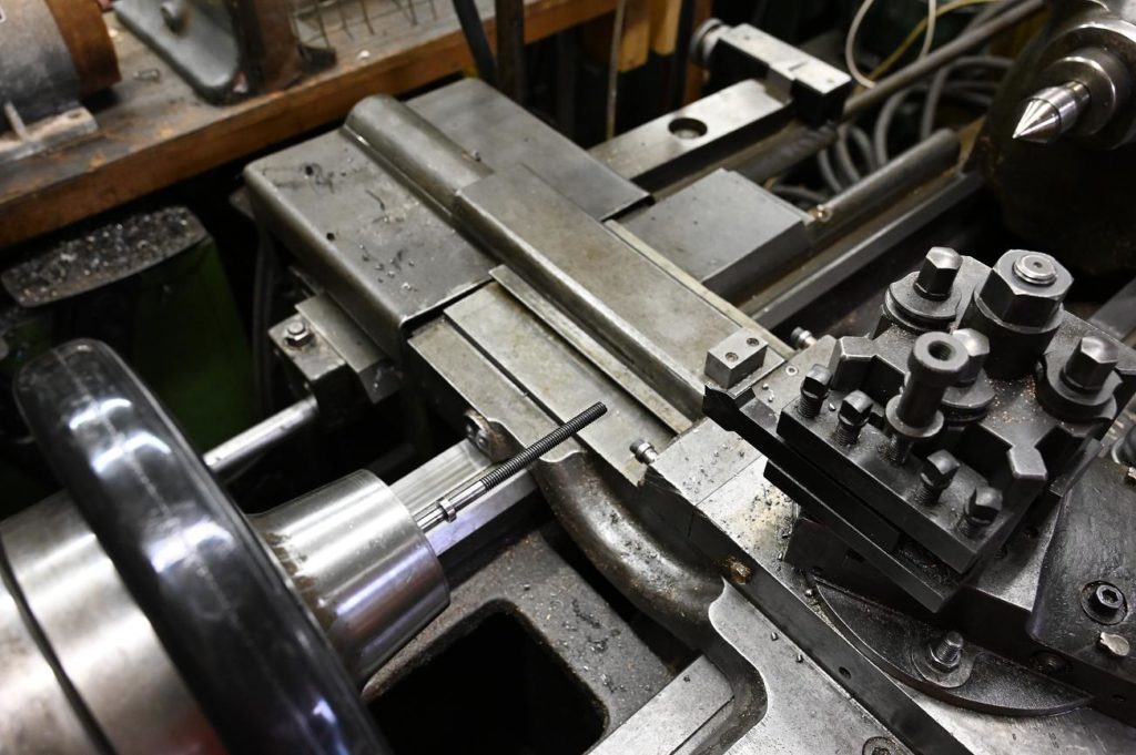
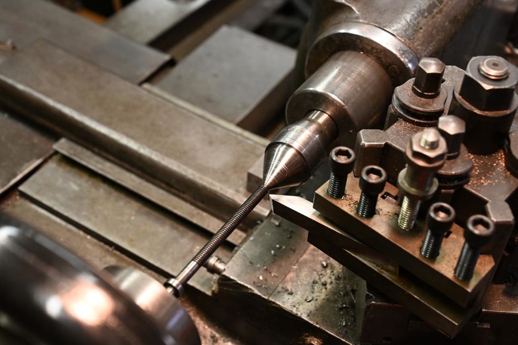
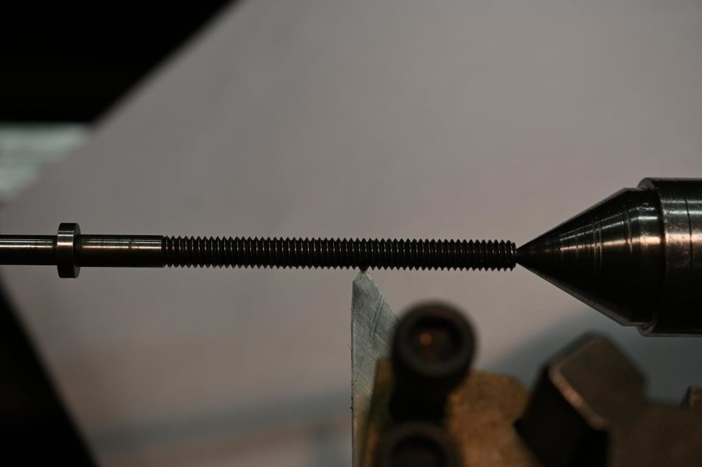
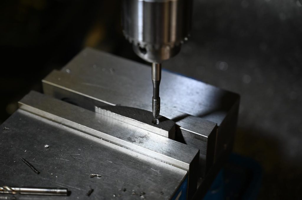
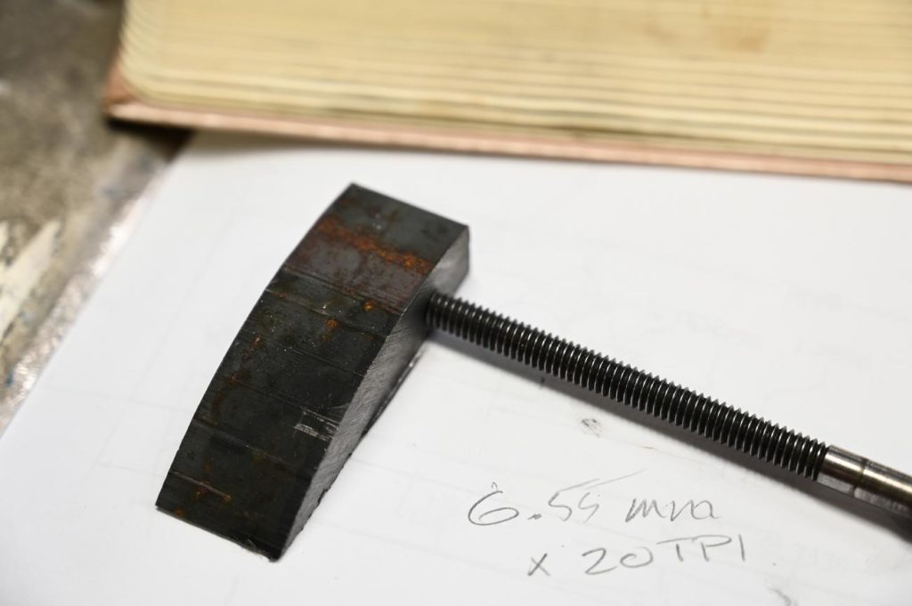
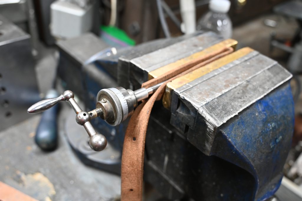
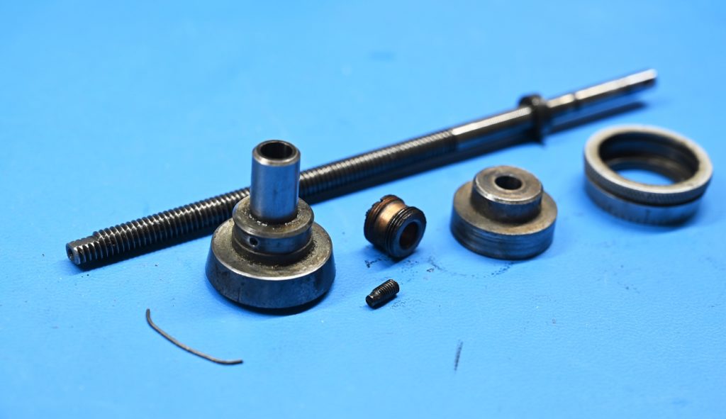
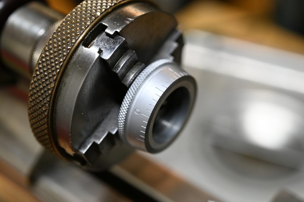
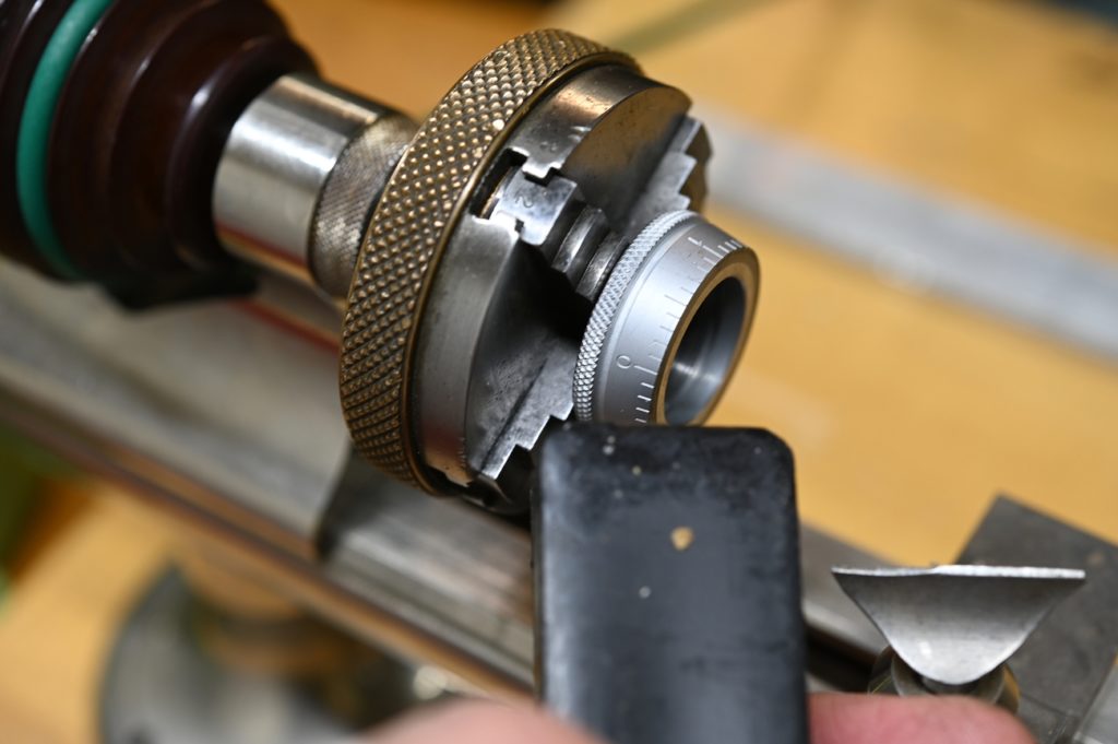
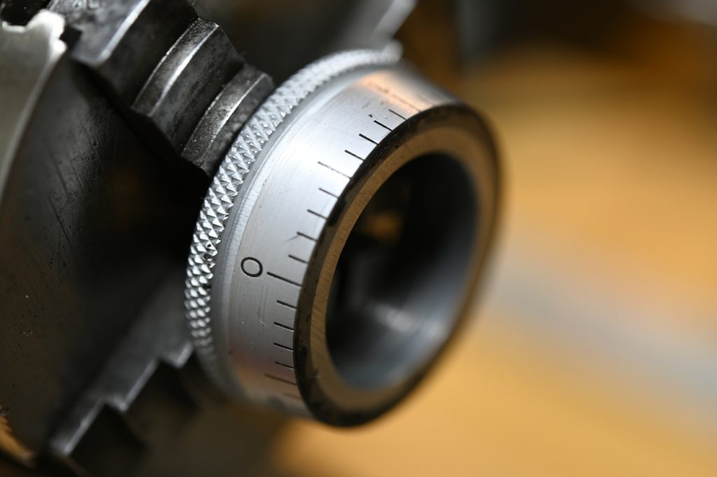
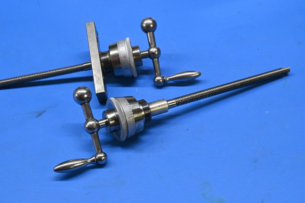
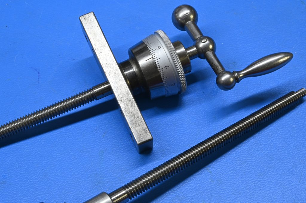
Dials and Feed Screw Assembly
These can be challenging to get apart. Here I’m using some leather to hold the screw will pulling of the handle.
Like the rest of the this lathe, the parts were a filthy mess
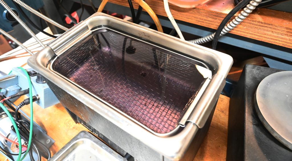
The first step is a run through the ultrasonic cleaner. I’m using some diluted degreaser
After degreasing all burrs and mars on the mechanical parts were removed by turning or polishing.
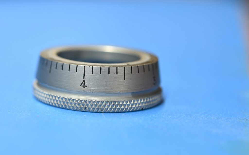
I did not however touch the dial surfaces and they are plated and we don’t want to damage that surface
Lorem ipsum dolor sit amet, consectetur adipiscing elit. Ut elit tellus, luctus nec ullamcorper mattis, pulvinar dapibus leo.
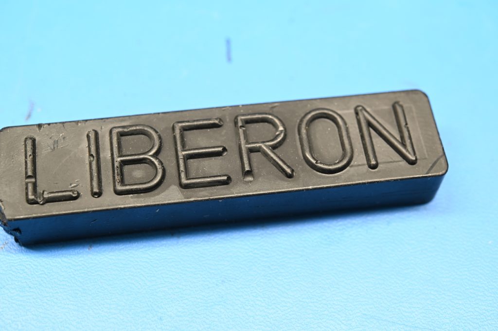
Start with some black furniture repair wax
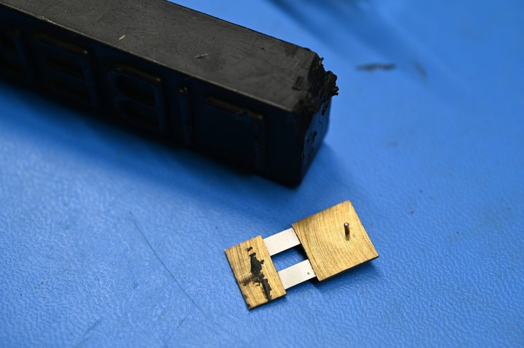
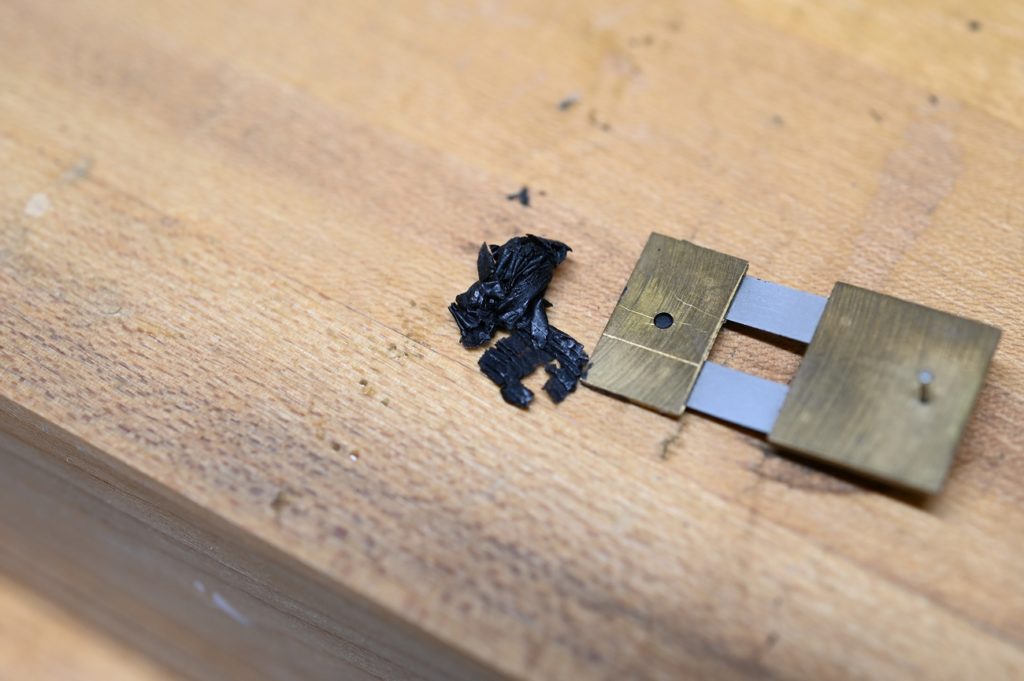
You also need a small sharp brass scraper, it should be brass so it will not damage the dial plated surface. I’m using a clock suspension spring (what the pendulum hangs from) just because it was handy
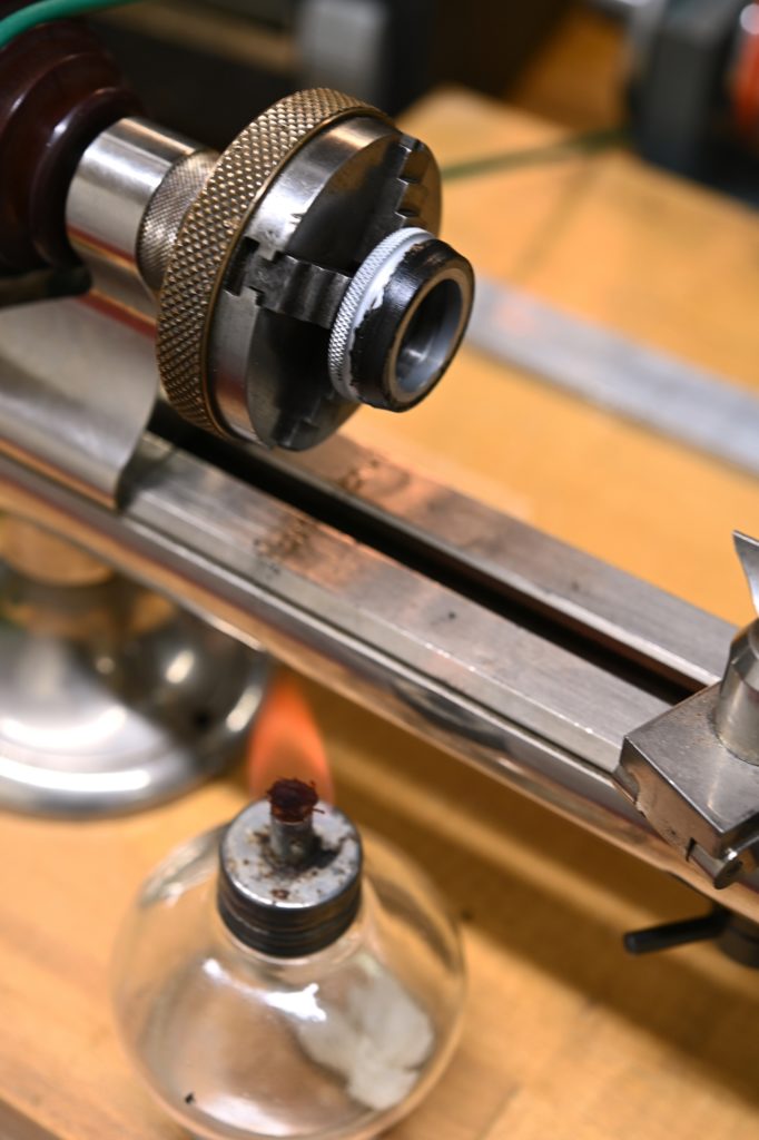
With an alcohol lamp, warm the dial and with the lathe slowly rotating, build up a layer of wax on the graduated portion of the dial. Keep it away from the knurling
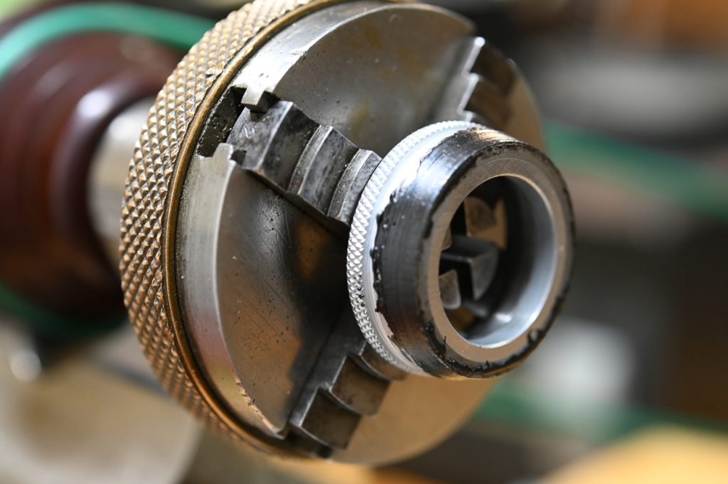
Now, with the work rotating, come in with the brass (just hand held) and scrape away the excess wax